Control device and method for a vibratory machine

The technology of a vibration generator and a control unit, which is applied to the device in the direction of travel and the control field of the unbalanced mass adjustment device, can solve the problems such as the uncontrollable adjustment of the moving speed.

Inactive Publication Date: 2005-08-31
德国宝马格公司
View PDF2 Cites 2 Cited by
  • Summary
  • Abstract
  • Description
  • Claims
  • Application Information

AI Technical Summary

Problems solved by technology

However, it cannot adjust the movement speed in a controllable manner

Method used


Image

  • Control device and method for a vibratory machine
  • Control device and method for a vibratory machine
  • Control device and method for a vibratory machine

Examples


Embodiment Construction

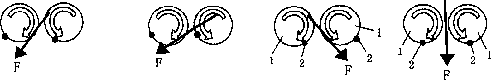
[0025] figure 1 It is schematically shown how a vibration generator, in particular a soil compactor with vibrating plates, moves forwards and backwards. Vibration occurs by turning the unbalanced mass 2 vibrating plates with opposite directions of rotation. A centrifugal force F of the unbalanced masses 2 is generated depending on the phase angle of the unbalanced masses 2 with respect to each other. In the case of in-situ vibration, the centrifugal force F generated acts in the vertical direction. As the vibration generator moves back and forth, the generated centrifugal force F is inclined to the vertical direction at a certain inclination angle so that the generated centrifugal force F not only has a vertical vibration component, but also generates a horizontal vibration component, causing the vibration generator to move.

[0026] Such as figure 1 As shown, the two unbalanced mass axes 1 move in the opposite direction to the unbalanced mass 2 indicated by the dot. The u...


PUM


Abstract

This invention relates to a control unit for an unbalanced mass adjusting device in a vibration generator, in particular in a soil compaction machine, having an adjusting cylinder which is hydraulically adjustable to adjust a relative position of contrarotating unbalanced masses in the vibration generator, having a control valve to adjust the adjusting cylinder so that the vibration behavior of the vibration generator is adjusted and having a control unit for triggering the control valve according to a pulse width modulation signal to adjust the relative position of the unbalanced masses as a function of the pulse duty factor of the pulse width modulation signal.

Description

technical field [0001] The invention relates to a control unit of an unbalanced mass adjustment device of a vibration generator, in particular in a device for controlling the direction of travel of a soil compactor. The invention also relates to a control method of the unbalanced mass adjustment device of the vibration generator. Background technique [0002] Soil compactors generally have vibrating plates that move at a frequency to compact the soil by vertical impact. This compaction is performed by vertically oriented vibration of the vibrating plate produced by a pair of opposing unbalanced mass axes. Unbalanced masses rotate synchronously but in opposite directions, resulting in centrifugal force in one direction of vibration. Through the phase displacement of the unbalanced mass, the vibration direction can be adjusted as required to possibly deviate from the vertical direction of vibration, so that in addition to the vertical component of vibration, a horizontal com...

Claims


Application Information

Patent Timeline
Patent Type & Authority Applications(China)
IPC IPC(8): E02D3/074B06B1/16E01C19/28F16H33/10
CPCE02D3/074B06B1/166Y10T74/18552
Inventor 尼尔斯·劳格维茨
Owner 德国宝马格公司
Why Eureka
Try Eureka