Inertial rotation axial braking device for gardening tool

A technology of rotating axial and garden tools, applied in the direction of brake types, brake actuators, brake components, etc., can solve the problems of inconvenient processing and maintenance, complex manufacturing structure, high manufacturing cost, etc., and achieve high braking reliability , simple structure and convenient maintenance

Inactive Publication Date: 2005-09-07
CHANGZHOU CREATE ELECTRIC APPLIANCE
View PDF0 Cites 13 Cited by
  • Summary
  • Abstract
  • Description
  • Claims
  • Application Information

AI Technical Summary

Problems solved by technology

There are mechanical brake devices, but the structure of the currently disclosed mechanical brake devices is relatively complicated, the reliability is poor, and the processing and maintenance are not convenient.
The disadvantages of other axial braking devices are: 1. The manufacturing structure is complicated and the manufacturing cost is high; 2. Since the elastic force of the spring is used to brake the brake, the spring force will decrease with time and eventually fail

Method used


Image

  • Inertial rotation axial braking device for gardening tool
  • Inertial rotation axial braking device for gardening tool
  • Inertial rotation axial braking device for gardening tool

Examples


Embodiment 1

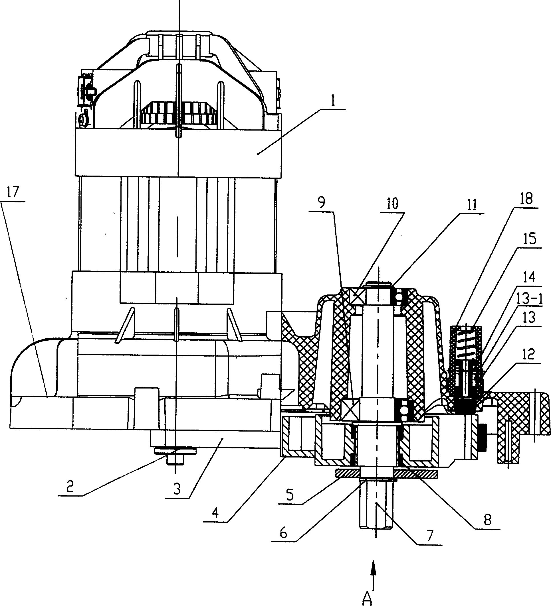
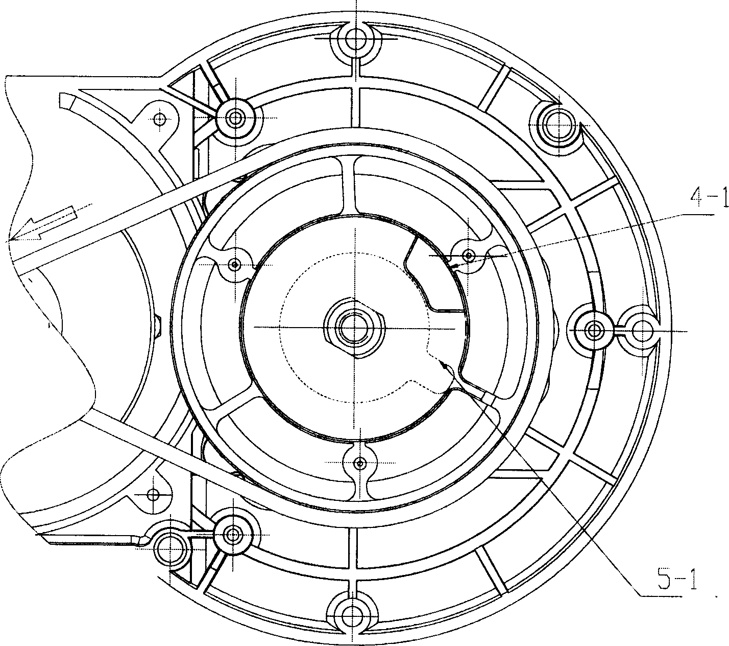
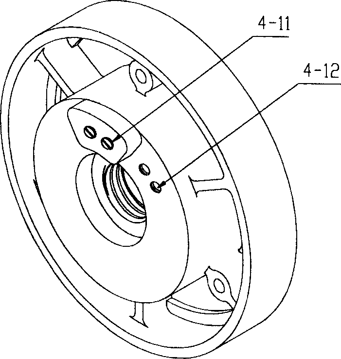
[0020] (see figure 1 ) an inertial rotation axial braking device for a garden tool, which is composed of a working shaft 7 for installing a tool, a driven wheel 4, a housing 17 and a brake block, the working shaft 7 for installing a tool is connected to the housing 17 in rotation, braking The block is located on the shell 17, the working shaft 7 is threaded 7-4 with the driven wheel 4, the outer end face of the driven wheel 4 is provided with a protrusion 4-1, the working shaft 7 is fixedly provided with a dial 5 and is arranged on The rotation plane of dial member 5 can be positioned within the height range of protrusion 4-1. In this embodiment, the brake block is composed of movable pin 13, limit pin 14, spring 15 and movable pin seat 18. The movable pin seat 18 Set on the casing 17, the movable pin 13 and the spring 15 are arranged in the movable pin seat 18, the spring 15 is arranged between the movable pin 13 and the bottom of the movable pin seat 18, and a limit sliding ...

Embodiment 2

[0022] (see figure 1 ) an inertial rotation axial braking device for a garden tool, which is composed of a working shaft 7 for installing a tool, a driven wheel 4, a housing 17 and a brake block, the working shaft 7 for installing a tool is connected to the housing 17 in rotation, braking The block is located on the shell 17, the working shaft 7 is threaded 7-4 with the driven wheel 4, the outer end face of the driven wheel 4 is provided with a protrusion 4-1, the working shaft 7 is fixedly provided with a dial 5 and is arranged on The rotation plane of dial member 5 can be positioned within the height range of protrusion 4-1. In this embodiment, the brake block is composed of movable pin 13, limit pin 14, spring 15 and movable pin seat 18. The movable pin seat 18 Set on the casing 17, the movable pin 13 and the spring 15 are arranged in the movable pin seat 18, the spring 15 is arranged between the movable pin 13 and the bottom of the movable pin seat 18, and a limit sliding ...

Embodiment 3

[0024] (see figure 1 ) an inertial rotation axial braking device for a garden tool, which is composed of a working shaft 7 for installing a tool, a driven wheel 4, a housing 17 and a brake block, the working shaft 7 for installing a tool is connected to the housing 17 in rotation, braking The block is located on the shell 17, the working shaft 7 is threaded 7-4 with the driven wheel 4, the outer end face of the driven wheel 4 is provided with a protrusion 4-1, the working shaft 7 is fixedly provided with a dial 5 and is arranged on Can make the rotation plane of dial piece 5 be positioned at the position within the height range of protrusion 4-1, in the present embodiment, (referring to Figure 7 ) The brake block adopts a friction plate 12 and the friction plate 12 is arranged on the end face of the driven wheel 4 opposite to the movable pin 13, and a reed 19 is provided on the housing 17 and the reed 19 is located at a position where it can overlap with the friction plate 12...


PUM


Abstract

The invention discloses a garden tool used rotating axial direction brake device that is made up of working shaft, driven wheel, casing and brake block. The working shaft connects rotating connects to the casing, and the brake block is set on the casing. The working shaft screw connects to driven wheel. Bulges are set on the out surface of the driven wheel. Moving component is fixed on working shaft. When the power for the invention is cut, inertia difference is existed between working shaft and the rotators installed on the working shaft to the driven wheel, and causes relatively rotating between working shaft and driven wheel. Then, the driven shaft would move to the axial direction until contacting to the brake block. Thus, the requirement for the material quality would be declined. And it is simple structure and is easy to machined and maintained.

Description

technical field [0001] The invention relates to a braking device for a garden tool, in particular to an inertial rotation axial braking device for a garden tool. Background technique [0002] After the power source of the garden tool is cut off, its working axis will not stop soon due to inertia. But there are some devices with special requirements, after the power source is cut off, the rotating part installed on the working shaft can stop rotating quickly. For example, the lawn trimmer belonging to garden electric tools, the rotating part is the blade, and the working shaft and the motor shaft are driven by a belt. It is required that the blade stop rotating within 3 to 5 seconds after the power of the motor is cut off. Some devices help with quick braking. Among them, electronic braking devices are used, but once the electronic components fail, the phenomenon of "seizure" will occur, resulting in damage to the motor. There are mechanical bra...

Claims


Application Information

Patent Timeline
Patent Type & Authority Applications(China)
IPC IPC(8): A01D34/68A01D69/10F16D65/092F16D65/14
CPCF16D2127/002F16D65/18A01D34/6812F16D2121/14
Inventor 葛树兴
Owner CHANGZHOU CREATE ELECTRIC APPLIANCE
Why Eureka
Try Eureka