
Device on spinning pre-processor for example a tufted pile feeding machine with a feeding apparatus

A technology of feeding device and feeding machine, which is applied in the direction of fiber processing, deburring device, fiber opening and cleaning machine, etc., can solve the problems of fiber material tension relaxation and error, and achieve the effect of trouble-free operation and leveling effect

Inactive Publication Date: 2005-09-14
TRUTZSCHLER GMBH & CO KG
View PDF0 Cites 6 Cited by
  • Summary
  • Abstract
  • Description
  • Claims
  • Application Information

AI Technical Summary

Problems solved by technology

Especially in the case of low flow rates, there is considerable time available before the next process, which also inevitably leads to a greater relaxation of the tension on the fiber material
In practice, when system settings are designed for high through-flow velocities, the outflowing clumps are initially thrown upwards, which often leads to errors in the next process

Method used


Image

  • Device on spinning pre-processor for example a tufted pile feeding machine with a feeding apparatus
  • Device on spinning pre-processor for example a tufted pile feeding machine with a feeding apparatus
  • Device on spinning pre-processor for example a tufted pile feeding machine with a feeding apparatus

Examples


Embodiment Construction

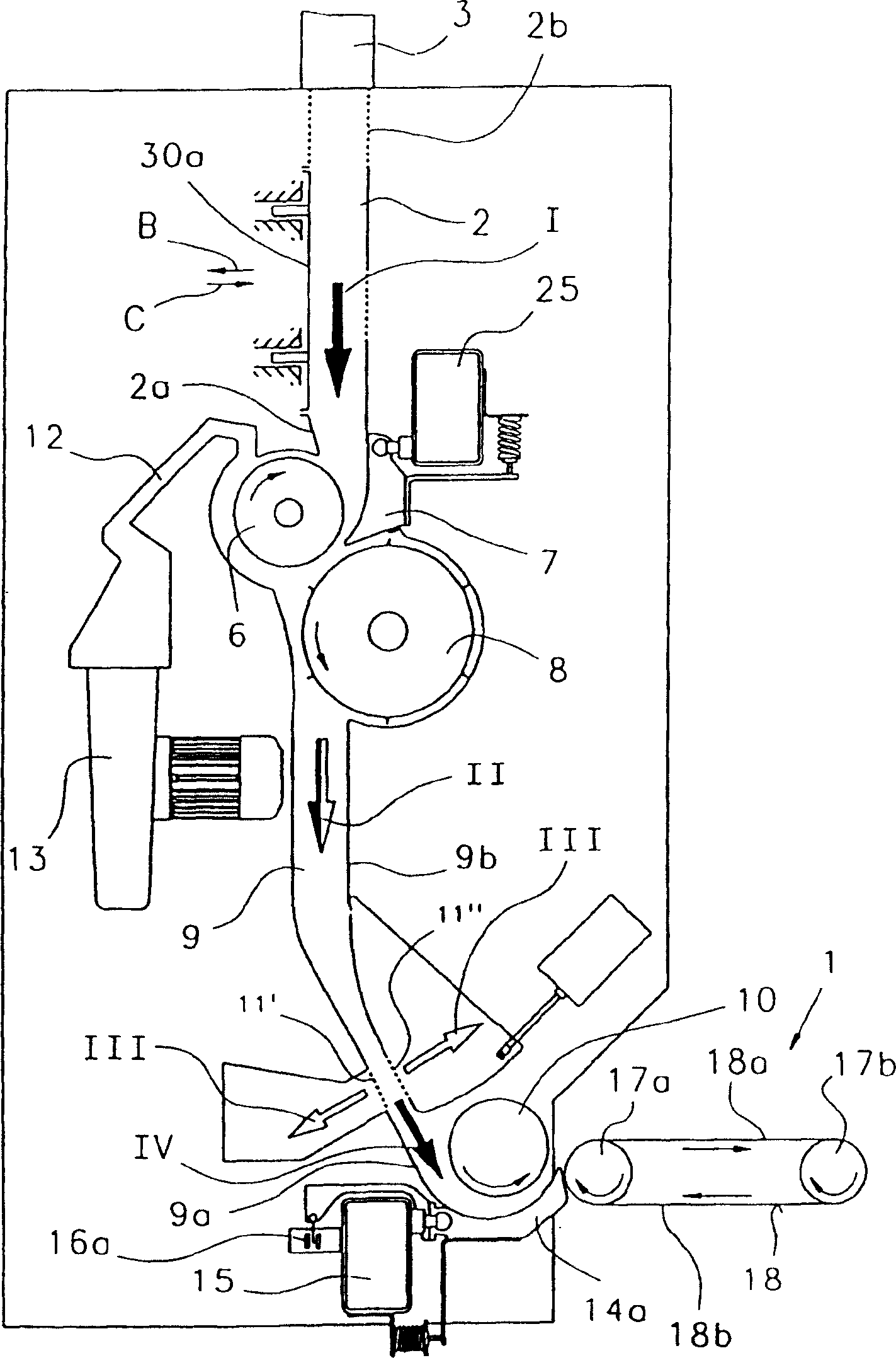
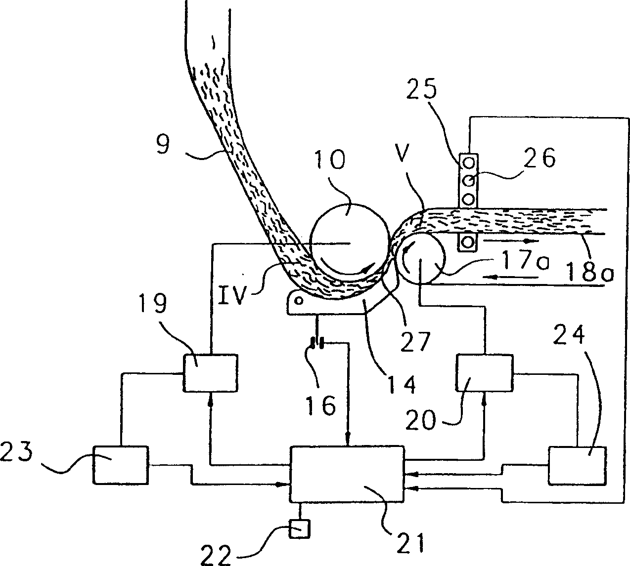
[0011] Such as figure 1 As shown, upstream of the continuously circulating conveyor belt 1 there is arranged a vertical storage tank 2 which is filled with finely opened fibrous material from above. Filling can take place, for example, via the supply and distribution line 3 by means of a collector. In the upper region of the storage tank 2 there is an air outlet 4 through which the conveying air, after being separated from the lint I, is passed into an extraction device. The lower end of the storage tank 2 is closed by an input roller 6 cooperating with an input disc 7 . Via this low-speed feed roller 6, the fibrous material can be fed from the storage tank 2 to a high-speed opening roller 8 located under the storage tank and covered with needles 8b or sawtooth wires (wire), said opening roller 8 at Part of its circumference is connected with a feed trough 9 below. The opening roller 8 rotates in the direction of the arrow 8a to convey the fibrous material III it collects i...


PUM


Abstract

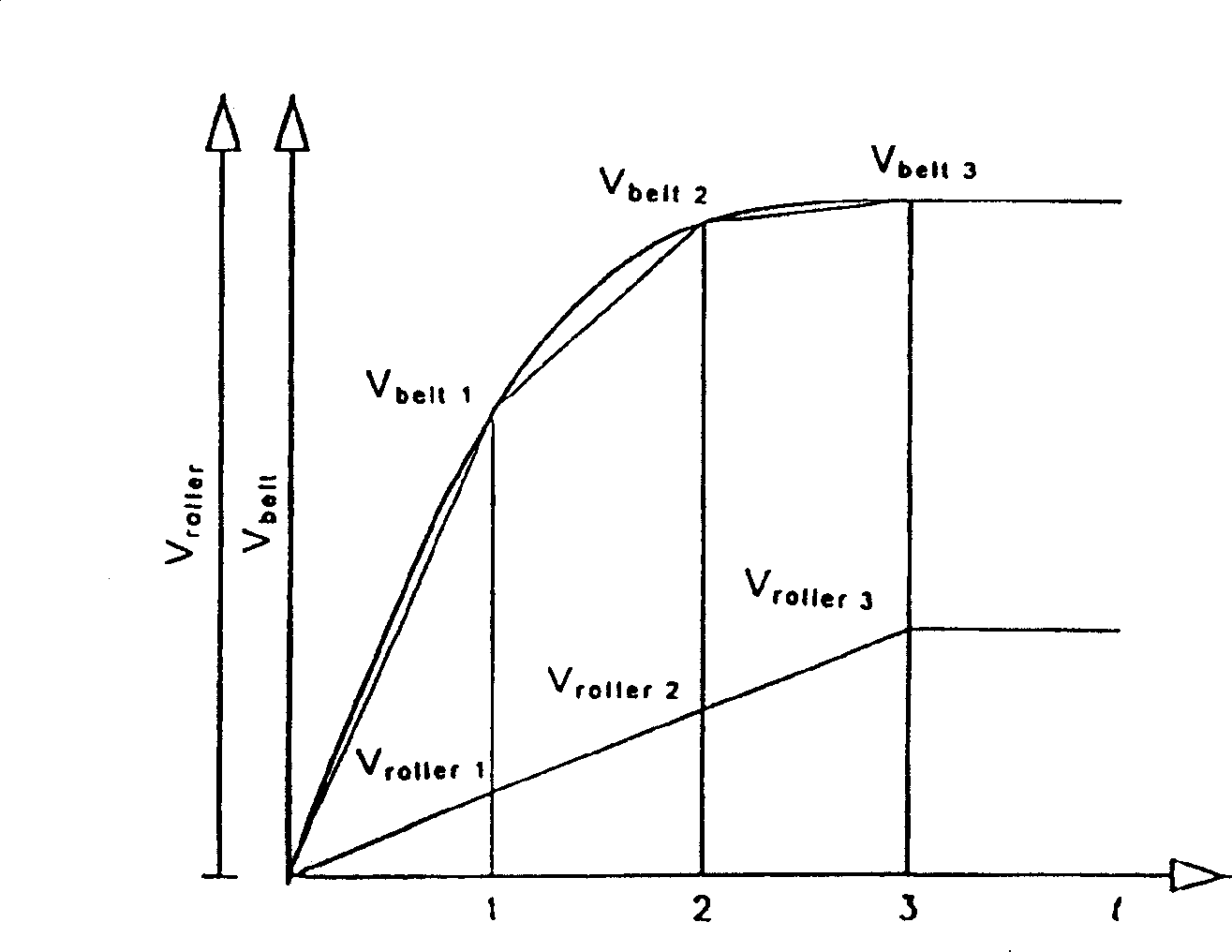
A spinning preparation machine, for example a tuft feeder, having a feed device comprising at least one slow-speed feed roller and a counter-element, for example a feed tray, with which fibre material can be supplied to a downstream transport device, has a driven transport element, for example a conveyor belt. In order to provide improved delivery from the feed device, or improved takeover by the downstream transport device, and to allow troublefree operation, for the purpose of determining setting values for the optimum speed of the transport element, a function between the measured values of the feed roller speed and the measured values of the transport speed is so determined that the fibre material lies on the moving surface of the transport element.

Description

technical field [0001] The present invention relates to an arrangement on a spinning machine, such as a tuft feeder, with a feeding device comprising at least one low-speed feed roller and an opposing feeder, such as a feeding pan. The element, via said low speed feed roller and its counter element, feeds the fibrous material to a downstream conveying device having a driven conveying element such as a conveyor belt. Background technique [0002] In systems for volumetric scanning of fiber streams, friction is unavoidable. When a continuous flow of fibrous material occurs, this friction causes the fibrous material to compress in the direction of flow. As soon as the fiber stream emerges from the gap of the roller / disk system, the tension on the fiber material is relaxed and the fiber material assumes an exit velocity higher than the peripheral velocity of the feed roller. Especially in the case of low flow rates, there is considerable time available before the next process ...

Claims


Application Information

Patent Timeline
Patent Type & Authority Applications(China)
IPC IPC(8): D01G15/40D01G9/16D01G9/18D01G23/00D01G23/02D01G23/04D01G23/06D01G25/00
CPCD01G15/40D01G23/04D01G23/02D01G9/16D01G23/00
Inventor 伯恩哈德·吕贝纳赫
Owner TRUTZSCHLER GMBH & CO KG
Learn More