Supercharge Your Innovation With Domain-Expert AI Agents!

Photoacoustic gas sensor, and a method for its production

A gas sensor, photoacoustic technology, applied in printed circuit parts, material analysis by optical means, material analysis using acoustic/ultrasonic/infrasonic waves, etc. energy and other issues, to achieve the effect of small size, low energy consumption and low cost

Inactive Publication Date: 2005-09-14
SIEMENS AG
View PDF2 Cites 0 Cited by
  • Summary
  • Abstract
  • Description
  • Claims
  • Application Information

AI Technical Summary

Problems solved by technology

The size of the gas sensor manufactured in this way is larger, and the gas sensor consumes more energy
In addition, the manufacturing process is complex, which can be seen in the price of the components

Method used


Image

  • Photoacoustic gas sensor, and a method for its production
  • Photoacoustic gas sensor, and a method for its production
  • Photoacoustic gas sensor, and a method for its production

Examples


Embodiment Construction

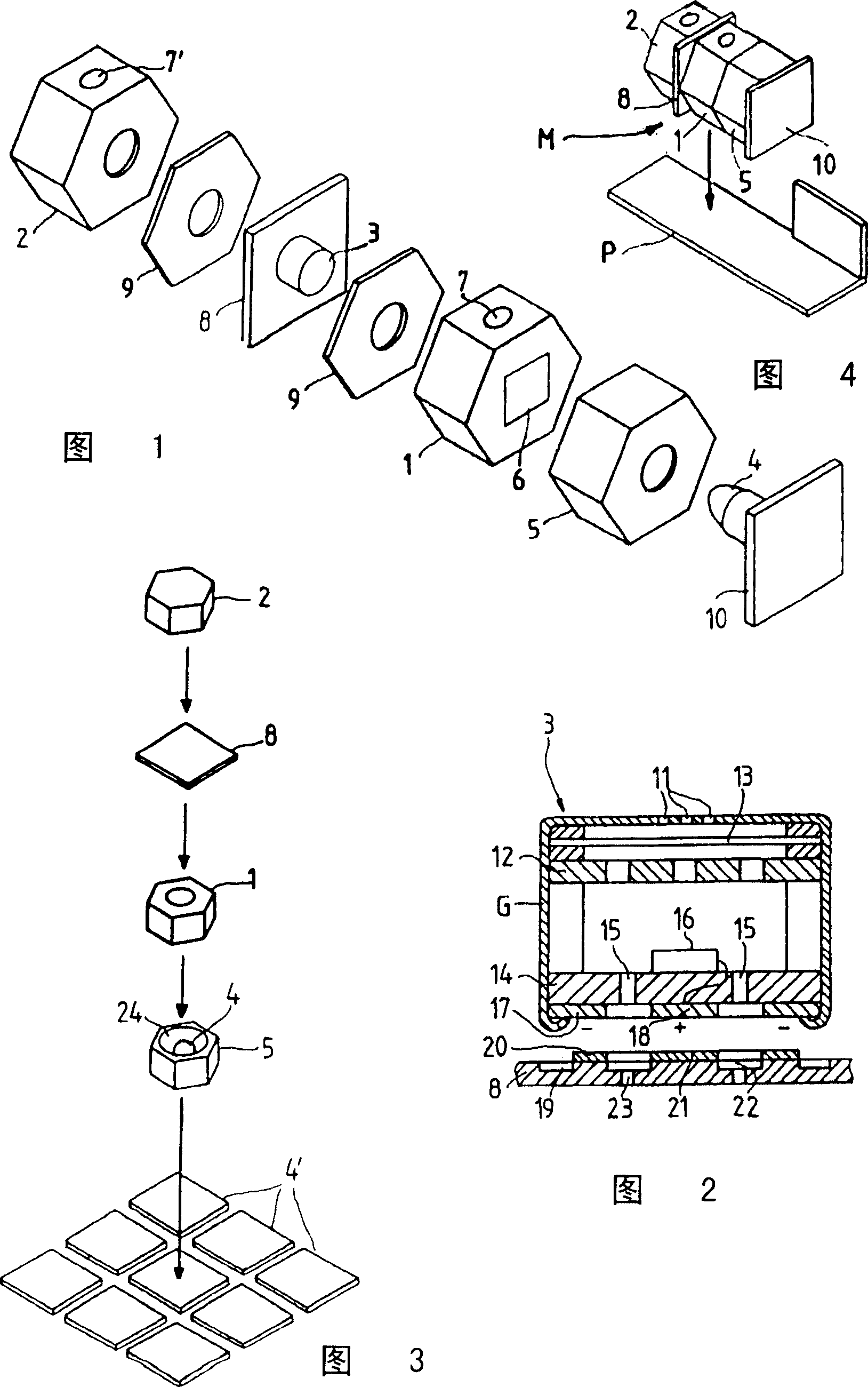
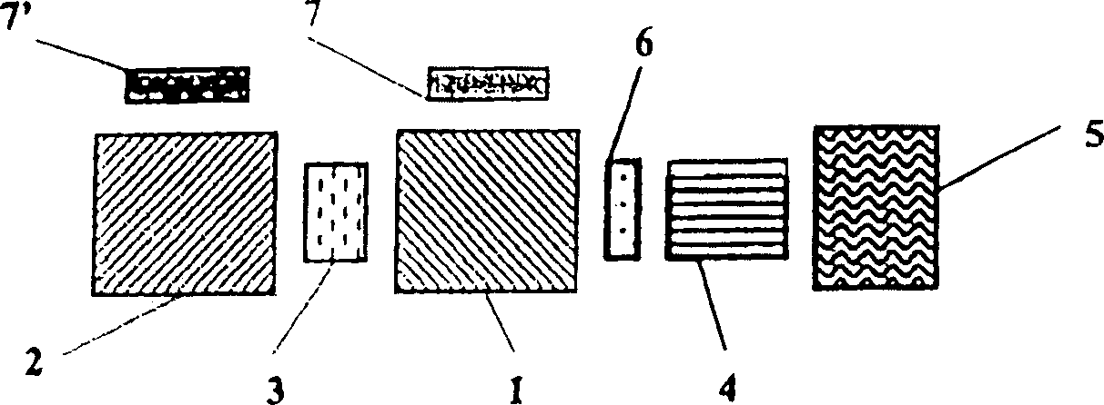
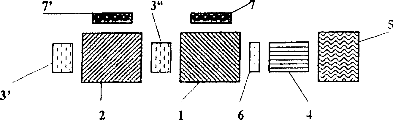
[0021] The acousto-optic gas sensor shown in Figure 1 includes a measuring element 1, a reference element 2, a two-way differential microphone 3 arranged between the two elements 1 and 2, a miniature incandescent lamp corresponding to the measuring element 1 4 and a reflector housing 5 with a reflector, wherein the reflector is used to focus the light emitted by the miniature incandescent lamp 4 onto a window arranged on the side wall of the measuring element 1 facing the miniature incandescent lamp 4, an infrared A bandpass filter 6 is inserted in this window. Measuring element 1 and reference element 2 are absolutely identical in terms of their design and dimensions. Both the measuring cell 1 and the reference cell 2 are provided with a window on an outer side wall, into which a gas-permeable membrane 7 or 7', respectively, is inserted. The differential microphone 3 is mounted on a printed circuit board 8 and a seal 9 is (optionally) provided on each of the two sides of the...


PUM


Abstract

A photoacoustic gas sensor has a measuring cell (1) and a reference cell (2), a light source (4) emitter and a microphone that measures the difference between the pressures of the measuring cell (1) and a reference cell (2). The microphone and light source (4) are manufactured on printed circuit boards (8, 10) of the microphone and a lamp, and are mounted on a printed circuit boards (P) together with the measuring and reference cells in a common module. The microphone includes a differential microphone(3) formed by a noise canceling microphone as the type used in cellphones. The method for manufacturing the photoacoustic gas sensor is characterized in that a measuring assembly (M) is composed of the light source (4) manufactured on the printed circuit board (10) of the lamp, the microphone manufactured on the printed circuit board (8) of the microphone, the measuring cell (1) and the reference cell (2) which are batch processed and assemble in advance, and the measuring assembly (M) is mounted on the assembly printed circuit boards (P).

Description

technical field [0001] The invention relates to a photoacoustic gas sensor having a measuring element and a reference element, a radiator and a microphone arrangement for measuring the pressure difference between the measuring element and the reference element. Background technique [0002] Photoacoustic gas sensors of the type mentioned at the outset have been produced in such a way that the microphone arrangement and the radiator are mounted on a base plate, the measuring element is then mounted around these components, and finally the reference element is attached thereto. The size of the gas sensor manufactured in this way is relatively large, and the gas sensor consumes more energy. In addition, the manufacturing process is complex, which can be seen in the price of the components. Contents of the invention [0003] It is an object of the present invention to provide a photoacoustic gas sensor of the type mentioned at the outset, which is characterized by small dimen...

Claims


Application Information

Patent Timeline
Patent Type & Authority Applications(China)
IPC IPC(8): G01NG01N21/17G01N21/37G01N25/00H05K1/14
CPCG01N21/1702G01N21/17G01N29/00
Inventor R·普莱施P·施泰纳
Owner SIEMENS AG
Features
  • R&D
  • Intellectual Property
  • Life Sciences
  • Materials
  • Tech Scout
  • Unparalleled Data Quality
  • Higher Quality Content
  • 60% Fewer Hallucinations
Learn More