Middle arranged sedimentation tank

A sedimentation tank, center-mounted technology, applied in the field of sedimentation tanks, can solve the problems of uneven water discharge and low surface load rate, and achieve the effect of uniform water distribution

Active Publication Date: 2005-09-21
SHANGHAI MUNICIPAL ENG DESIGN INST GRP
View PDF0 Cites 9 Cited by
  • Summary
  • Abstract
  • Description
  • Claims
  • Application Information

AI Technical Summary

Problems solved by technology

[0003] The purpose of this invention is to provide a new type of middle-mounted sedimentation tank, which can better improve the current problems of low surface load rate and uneven water discharge in sedimentation treatment.

Method used


Image

  • Middle arranged sedimentation tank
  • Middle arranged sedimentation tank
  • Middle arranged sedimentation tank

Examples


Embodiment Construction

[0010] The present invention will be further described below in conjunction with the accompanying drawings and embodiments.

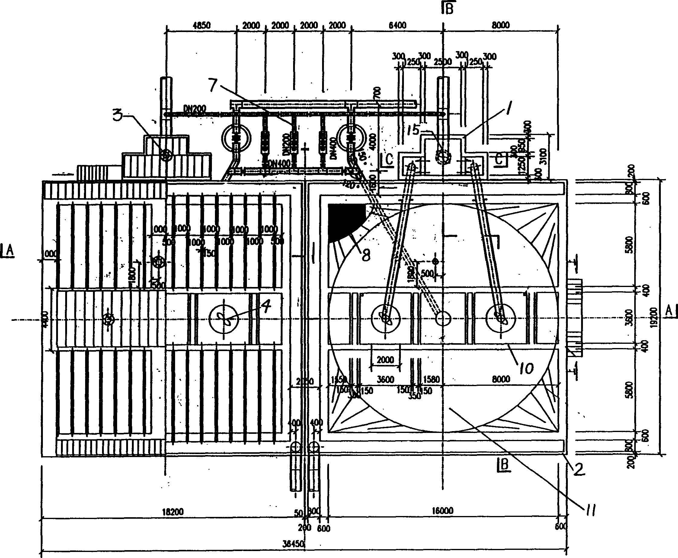
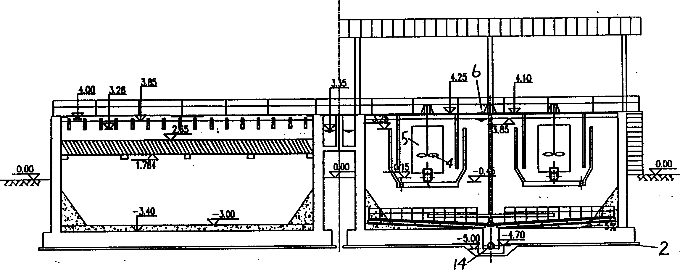
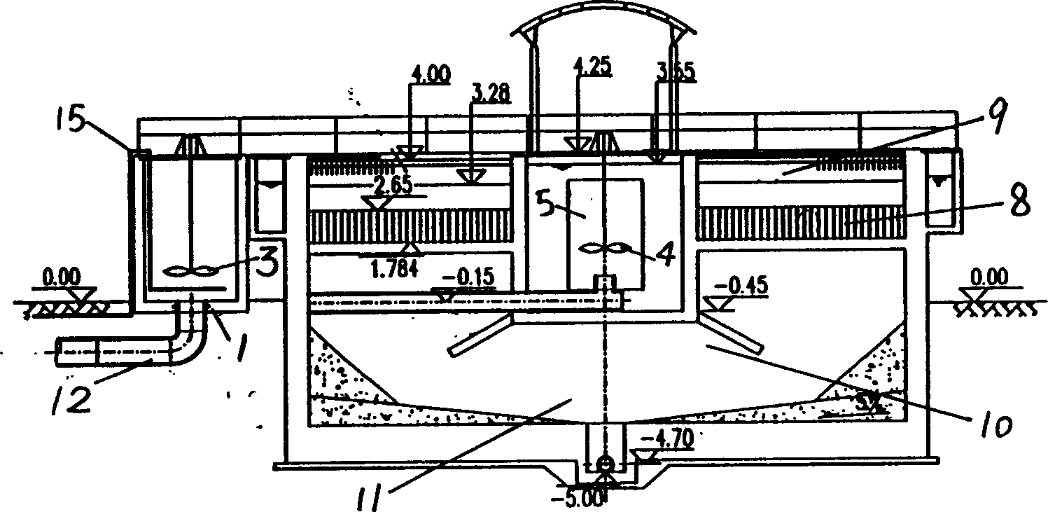
[0011] According to the present invention is a kind of mid-mounted reflux flocculation inclined tube sedimentation tank, such as figure 1 As shown, the mid-mounted sedimentation tank mainly includes a mixing tank 1, a main tank body 2, a mixing mixer 3 arranged in the mixing tank 1, a lifting mixer 4 arranged inside the main tank body 2, and a stainless steel agitator attached to the lifting mixer 4 Cylinder body 5, in the thickened mud discharge area 11 at the bottom of the main pool body 2, a mud scraper 6, a water distribution weir and baffle system 10 located on the upper part of the main pool body 2, and a plastic plastic material connected to the water distribution weir and baffle system 10 The inclined pipe area 8 and the stainless steel water outlet rectangular tank 9 are provided with a sludge screw pump 7 outside the tank body, which is connec...


PUM


Abstract

The invention discloses a built-in desilter, which is characterized in that lifting the agitator and its appendixes in the body tank such as a non-corrodible steel body, a sludge scraper, the plastic inclined tube area and a non-corrodible steel water outlet rectangular channel, arranging the mixing agitator in the mixture tank out of the body tank, connecting the sludge screw pump with incurrent siphon and concentrated sludge discharge area using a sludge pipe.

Description

Technical field: [0001] The invention relates to the technical field of sedimentation tanks, in particular to a water treatment tank used for mixed flocculation and sedimentation in conventional treatment in water supply plants and primary treatment in sewage plants. Background technique: [0002] At present, the conventional treatment of waterworks and the primary treatment of sewage plants mostly adopt traditional tank types such as advection sedimentation tanks, mechanical stirring clarifiers, and inclined tube sedimentation tanks. Among them, although the conventional water quality of the advection sedimentation tank can also meet the requirements of the water to be filtered, and it is easy to manage and resistant to impact loads, but it occupies a large area and has a large amount of sludge discharge, and the treatment effect on low-temperature and low-turbidity water is poor; mechanical agitation Although the clarification tank occupies a small area, it is difficult to...

Claims


Application Information

Patent Timeline
Patent Type & Authority Applications(China)
IPC IPC(8): B01D21/01B01D21/04C02F1/52
Inventor 郑毓佩许嘉炯沈裘昌雷挺肖敏杰任永青
Owner SHANGHAI MUNICIPAL ENG DESIGN INST GRP
Why Eureka
Try Eureka