Wavy subsurface-flow constructed wetland landscape water body treatment system and method

A technology of constructed wetland and treatment system, applied in biological water/sewage treatment, water/sludge/sewage treatment, aerobic and anaerobic process treatment, etc. It can increase the hydraulic retention time, promote the deposition of phosphorus, and enhance the effect of sewage treatment.

Inactive Publication Date: 2014-06-18
TIANJIN UNIV
View PDF6 Cites 11 Cited by
  • Summary
  • Abstract
  • Description
  • Claims
  • Application Information

AI Technical Summary

Problems solved by technology

[0003] After searching the literature of the prior art, it is found that the existing artificial wetland sewage treatment method for treating landscape water bodies, such as CN201110370614.5, is a system and method for treating sewage in a composite horizontal subsurface flow artificial wetland. The main processing unit of the system is It includes a first-level horizontal subsurface flow wetland treatment unit and a second-level horizontal baffle wetland treatment unit connected in series. The first level horizontal subsurface flow wetland treatment unit is provided with a vertical flow nitrification zone, and most of the sewage is removed by the primary sedimentation tank. Sand particles and suspended particulate matter flow into the nitrification zone by gravity, and then use the first-level subsurface flow artificial wetland and the second-level horizontal baffle wetland treatment unit to complete the final treatment and removal function. This system has the advantages of low treatment cost, small footprint, and nitrogen removal Phosphorus removal effect is better and other advantages, but the structure is relatively complicated, and the advantages of horizontal subsurface flow constructed wetland and vertical subsurface flow constructed wetland are not fully combined; CN201010255219.8 discloses a landscape type composite constructed wetland treatment device for eutrophic water body and its application , the composite constructed wetland in this invention combines the surface flow and the horizontal subsurface flow constructed wetland vertically on the basis of a plane, superimposed and connected in series, and has the advantages of small footprint, high treatment efficiency, low construction cost, not easy to block, and stable operation However, surface flow constructed wetlands have the disadvantages of easy breeding of mosquitoes and flies and low nitrification capacity, and horizontal subsurface flow constructed wetlands have poor nitrification capacity; CN201020126627.9 combines horizontal subsurface flow constructed wetlands, vertical subsurface flow constructed wetlands and The surface flow artificial wetland is organically combined to form a composite wetland unit, which has the characteristics of good purification effect, simple structure, less prone to blockage, and convenient maintenance.
The existing technology mainly utilizes surface flow constructed wetlands, horizontal subsurface flow constructed wetlands, vertical subsurface flow constructed wetlands and their different forms. The sewage in surface flow constructed wetlands and horizontal subsurface flow constructed wetlands flows horizontally, resulting in lower nitrogen and phosphorus removal effects than vertical subsurface flow constructed wetlands. Subsurface flow constructed wetlands and vertical subsurface flow constructed wetlands have good nitrogen and phosphorus removal effects, but they dry out and flood for a long time, resulting in lower organic matter removal capacity than horizontal subsurface flow constructed wetlands.

Method used


Image

  • Wavy subsurface-flow constructed wetland landscape water body treatment system and method
  • Wavy subsurface-flow constructed wetland landscape water body treatment system and method
  • Wavy subsurface-flow constructed wetland landscape water body treatment system and method

Examples


Embodiment Construction

[0038] The present invention will be further described below in conjunction with the accompanying drawings and specific embodiments, but the protection scope of the present invention is not limited to the following specific embodiments.

[0039] Specific Embodiments The present invention is implemented by taking the landscape water body in a certain urban development zone in the north as the processing object.

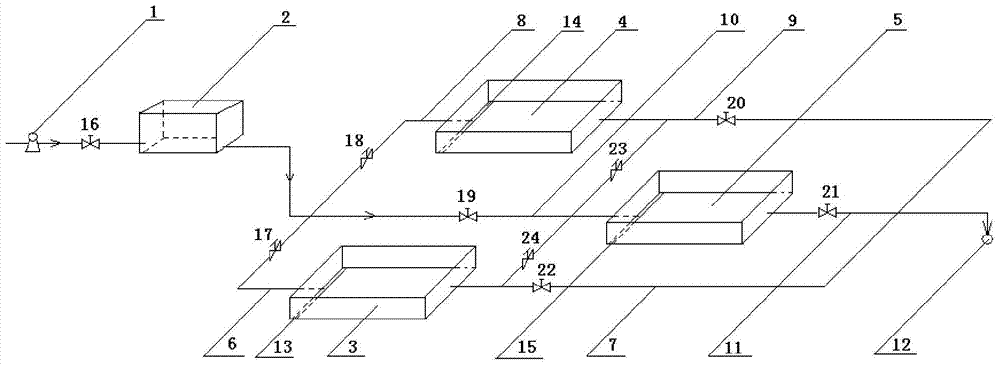
[0040] In this wave-type submerged flow artificial wetland sewage treatment system, a regulating tank (2) is connected to the outlet of the water pump (1), and the regulating tank (2) passes through the water inlet pipe A (6), the water inlet pipe B (8) and the water inlet pipe C respectively. (10) Connected with wave-type subsurface flow constructed wetland A (3), wave-type subsurface flow constructed wetland B (4) and wave-type subsurface flow constructed wetland C (5), the outlet pipe A (7) and outlet pipe of the wave-type subsurface flow constructed wetland The wat...


PUM

PropertyMeasurementUnit
particle diameteraaaaaaaaaa
heightaaaaaaaaaa
heightaaaaaaaaaa

Abstract

The invention discloses a wavy subsurface-flow constructed wetland landscape water body treatment system and method. The system combines a horizontal subsurface-flow constructed wetland with a vertical subsurface-flow constructed wetland to form a wavy subsurface-flow constructed wetland. By means of regularly arranging upper clapboards and lower clapboards inside the wetland and replacing a horizontal flow state with a wavy flow state, sludge flows in a plurality of modes which are connected in series and alternate in upstream and downstream flows, so that organic nutrient substances are sufficiently degraded to remarkably promote deposition of phosphorus; the sludge is repeatedly subjected to anaerobic and aerobic treatment, so that removing of nitrogen can be facilitated; appropriate limestone is added into the filler of the wetland to release Ca<2+>, so that phosphorus in the sludge generates insoluble deposition of calcium phosphate, and thus the removal rate of phosphorus is increased. Due to the adoption of modes, such as intermittent water distribution, water inflow to a water distribution pipe by forming openings in the bottom as well as serial or parallel operation of a plurality of wavy subsurface-flow constructed wetlands, the bed body of the constructed wetland plays a relatively large efficiency, the removal rate of nitrogen phosphorus and organic matters is increased and the sludge treatment capability is enhanced.

Description

technical field [0001] The invention belongs to the technical field of environmental protection, and in particular relates to a wave-type subsurface flow artificial wetland sewage treatment system and a treatment method for treating landscape water bodies. Background technique [0002] Landscape water bodies are mostly static or closed slow-flowing water bodies with poor fluidity, which means that they are easily polluted, have poor self-purification ability, and have low water environment capacity. Landscape water bodies are generally located in densely populated areas. Due to the bad habits of residents and the injection of surrounding pollutants, the landscape water bodies are seriously polluted and prone to eutrophication, seriously affecting their landscape functions. Constructed wetland is an environment-friendly sewage treatment technology with low treatment cost and infrastructure cost. It uses the physical, chemical and biological triple synergies of substrate-aquat...

Claims


Application Information

Patent Timeline
Patent Type & Authority Applications(China)
IPC IPC(8): C02F3/32C02F3/30
CPCY02W10/10
Inventor 王晓欧许吟波赵楠彭森赵新华
Owner TIANJIN UNIV
Why Eureka
Try Eureka