

Electromagnetic wave reflecting surface capable of realizing high directionality and multi-frequency band
A reflective surface and multi-band technology, applied in the direction of electrical components, antennas, etc., can solve the problems of large volume, inability to achieve high directional radiation of a single antenna, and inability to achieve the isolation effect of microwave circuit components, achieving high efficiency and low cost Effect
- Summary
- Abstract
- Description
- Claims
- Application Information
AI Technical Summary
Problems solved by technology
Method used
Image

Examples
Embodiment 1
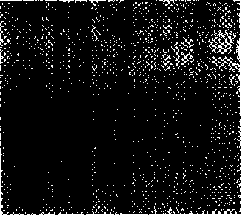
[0032] Please refer to the attached figure 1 . The present invention is an electromagnetic wave reflecting surface composed of a 5-degree symmetrical quasi-periodic structure arrangement, which is composed of a metal patch on the upper surface, a metal base plate on the lower base plate, and a metallized guide hole connecting the upper and lower metal layers. The structure does not have translational symmetry. only have rotational symmetry. The two types of diamonds on the upper surface have the same side length of 7.366 mm, and the acute angles are 36 degrees and 72 degrees respectively. The density is 1.6 mm, the dielectric constant is 2.2, and the area size of the entire sample is 190.0×190.0 mm2. The invention adopts the monopole and the dipole antenna to respectively carry out the surface wave measurement of TM and TE modes. In TM surface wave measurement, two monopole antennas are used as transmitting and receiving antennas respectively on the measured material of the...
Embodiment 2
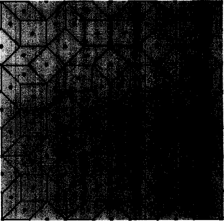
[0035] Please refer to the attached figure 2 . The present invention is an electromagnetic wave resonant surface composed of octave symmetrical quasi-periodic arrangement, and the structure arrangement is the same as figure 1 , which are composed of rhombuses with acute angles of 45 degrees and 90 degrees respectively, the side length of the rhombus is 7.62 mm, the slot spacing is 0.508 mm, the diameter of the guide hole is 0.7 mm, the thickness is 1.6 mm, the dielectric constant is 2.2, and the material area is 204.6×204.6 square millimeters.
[0036]The measurement results of the surface wave transmission spectrum are as follows Figure 9 , where the TM surface wave transmission spectrum of the metal surface is shown as the curve marked by the triangle, the circle marks the TM surface wave transmission spectrum measurement curve on the 8-degree quasi-periodic structure, and the square marks represent the TE surface wave on the 8-degree quasi-periodic structure The transm...
Embodiment 3
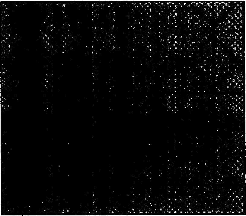
[0039] Please refer to the attached image 3 , 4 and 5. The upper surface of the present invention is composed of two kinds of resonant units of triangle and pentagon with Figure 4 with Figure 5 The symmetrical structure is arranged periodically. The metal patch on the upper surface is connected to the metal of the lower base plate through metallized guide holes. Their area ratio is 1:2. They are divided into square resonant units according to this ratio. The square The side length of the unit is 6.6 mm, the distance between the two resonant units in the figure is 0.6 mm, the diameter of the guide hole is 0.7 mm, the thickness of the board is 1.6 mm, the dielectric constant is 2.2, and the material area is 204.6×204.6 square millimeters.
[0040] Similarly, the self-made monopole antenna and dipole antenna are used to measure the surface wave transmission spectrum similar to the above measurement method, and the results are as follows Figure 10 shown. The straight line...
PUM
| Property | Measurement | Unit |
|---|---|---|
| Diameter | aaaaa | aaaaa |
| Acute angle | aaaaa | aaaaa |
| Thickness | aaaaa | aaaaa |
Abstract
Description
Claims
Application Information