Eleastic expansion meshing body pile connecting end plate and prefab

A prefabricated and elastic technology, applied to sheet pile walls, foundation structure engineering, construction, etc., can solve problems such as incomplete butt joints and sinking of pipe piles, and achieve the elimination of broken piles, accurate distribution, and integrity and strength Effect

Inactive Publication Date: 2005-10-05
周兆弟
View PDF1 Cites 4 Cited by
  • Summary
  • Abstract
  • Description
  • Claims
  • Application Information

AI Technical Summary

Problems solved by technology

The fly in the ointment is: for the soft ground, especially the first pipe pile, when the ground bearing pressure is less than the insertion expansion force of the expansion screw, the pipe pile will sink and cannot be fully and reliably docked

Method used


Image

  • Eleastic expansion meshing body pile connecting end plate and prefab
  • Eleastic expansion meshing body pile connecting end plate and prefab
  • Eleastic expansion meshing body pile connecting end plate and prefab

Examples


Embodiment 1

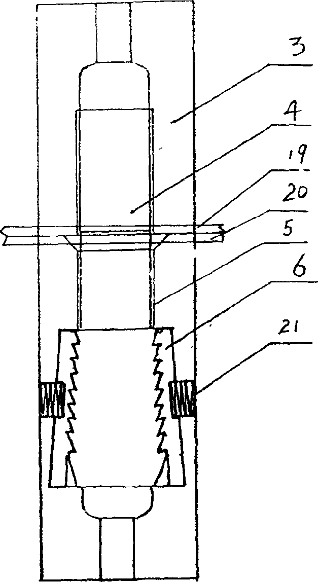
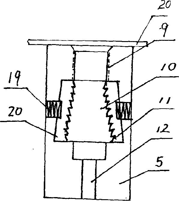
[0016] Embodiment 1: with reference to attached Figure 1~6 . Elastic expansion engaging body piling end plate, which includes end plates 19 and 20, 2 or more expansion nuts 3 are distributed on the end plate 19, and the screw segments in the engagement screws 4 are screwed on the expansion nuts 3 Inside, two or more top pull nuts 5 are circumferentially distributed on the end plate 20, the plug-in meshing tooth sleeve 6 is located in the expansion cavity 10 of the top pull nut 5, and the outside of the plug-in mesh tooth sleeve 6 is connected to the top pull nut There is a spring 21 between the 5 walls, usually a compression spring, one end of the compression spring 21 is located in the hole in the wall of the top pull nut 5 and is in contact with the rivet at the end of the wall hole of the top pull nut, and the other end is in contact with the plug-in meshing tooth sleeve The outer sides are in contact, and when docking, the plug-in meshing sleeve 22 is located in the expa...

Embodiment 2

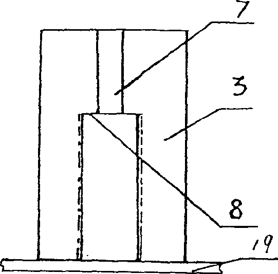
[0017]Embodiment 2: with reference to accompanying drawing 7. On the basis of Embodiment 1, the prefabricated part composed of elastic expansion engagement body pile end plates, the two ends of the prefabricated part 17 are respectively equipped with end plates 19 with a plurality of tension nuts 3 and with a plurality of top pull nuts. The end plate 20 of the nut 5, the headers 2 at both ends of the longitudinal steel bars 18 in the prefabricated part 17 are respectively clipped on the steel bar header clamps 8 and 11 in the expansion nut 3 and the top pull nut 5, and meshed Screw 4 is used for the docking between two prefabricated parts 17. The screw section of the engagement screw 4 is screwed into the tension nut 3, and the engagement section of the engagement screw is inserted into the plug-in engagement gear sleeve 20 in the top pull nut and elastically engages with the insertion engagement gear sleeve (the engagement screw 4 is in the pipe pile When docking with the pi...

Embodiment 3

[0018] Embodiment 3: with reference to accompanying drawing 8. On the basis of Examples 1 and 2, the butt joint structure between the prefabricated part and the prefabricated part composed of the elastic expansion engaging body pile end plate, the ends of the two prefabricated parts to be butted are respectively equipped with top tension expansion bolts. The end plate of the cap and the end plate with the expansion nut, the opening of the expansion nut on the end plate of one preform is opposite to the opening of the expansion nut on the end plate of the other preform, and engage The screw section of the screw is screwed into the threaded buckle of the pull-up nut, and the meshing tooth section of the meshing screw is inserted into the plug-in meshing sleeve in the top-pull nut and elastically engages with the plug-in meshing sleeve to complete the prefabricated part and the prefabricated connection between pieces.


PUM


Abstract

The invention relates to tubular interface, the pre-make part, which is made of pre-make part's interface and the connection instruction between the pre-make parts as well as the facture of the pre-make part. It comprises end board, two or more inflation draw crew caps and the top draw screw cap which distribute circumferentially on the end board, and the screw part of inflation mesh screw connects convolutedly into the inflation draw crew cap. The mesh alveolus locates in the cavity of the top draw screw cap. The insert-style mesh alveolus locates in the inflation cavity of the top draw screw cap. There is a spring sets between the outside of the alveolus and the wall of the top draw screw cap. When they are face-to-face connected, the insert-style mesh alveolus locates in the inflation cavity of the top draw screw cap, the mesh tooth part of mesh screw inserted in the insert-style mesh alveolus of the insert-style top draw screw cap and meshes with the mesh teeth in the alveolus. The two ends of the pre-make part have end-stake with many inflation draw screw caps and the pre-make part with many top draw screw caps respectively. In the pre-make part, there are many items of the portrait reinforcing steel bar whose two ends clip to the steel cap of the inflation draw screw caps and the top draw screw cap respectively. The mesh screw is used to the face-to-face connection of two pre-make parts.

Description

Technical field: [0001] The invention relates to a pipe pile joint, a prefabricated plate joint, a bridge pier joint, a bridge joint, an electric pole interface and its prefabricated parts, and a pipe pile joint, a prefabricated plate joint, a bridge pier joint and a bridge joint. The pipe pile and the connection between the pipe pile and the pipe pile, the connection between the prefabricated slab and the prefabricated slab, the connection between the bridge pier and the bridge pier, the connection structure between the prefabricated pole and the prefabricated pole and the production of prefabricated parts The method belongs to the fields of prefabricated part fastening and prefabricated part manufacturing. Background technique: [0002] This application is based on the applicant's patent application number 200410091063.9 and the name "upper screw and lower top connection pile buckle and prefabricated parts". It consists of an expansion nut, an expansion screw and a top ten...

Claims


Application Information

Patent Timeline
Patent Type & Authority Applications(China)
IPC IPC(8): E02D5/30E02D5/52E04B1/38
Inventor 周兆弟
Owner 周兆弟
Why Eureka
Try Eureka