Exhaust gas throttle valve for engines

An exhaust throttle valve, engine technology, applied in the direction of engine components, engine control, combustion engine, etc., to achieve the effect of noise reduction

Inactive Publication Date: 2005-10-12
ISUZU MOTORS LTD
View PDF2 Cites 12 Cited by
  • Summary
  • Abstract
  • Description
  • Claims
  • Application Information

AI Technical Summary

Problems solved by technology

Such problems are common not only to exhaust throttle valves combined with continuous regenerative DPFs, but also to exhaust throttle valves equipped as exhaust brake valves, etc.

Method used


Image

  • Exhaust gas throttle valve for engines
  • Exhaust gas throttle valve for engines
  • Exhaust gas throttle valve for engines

Examples


Embodiment Construction

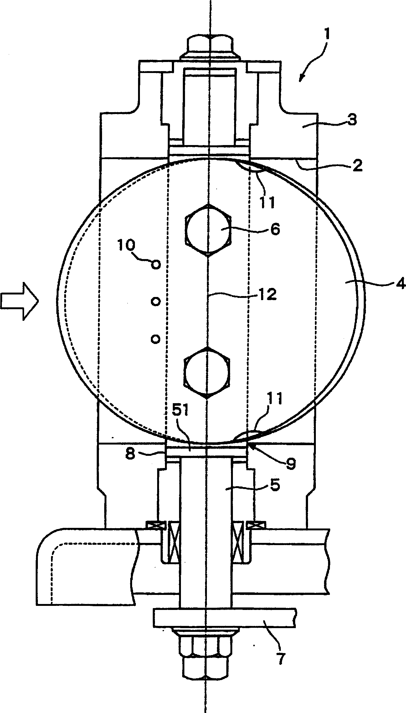
[0040] Hereinafter, an exhaust throttle valve according to the present invention will be described with reference to the drawings. However, the present invention relates to the exhaust throttle valve itself, the structure and action of the applicable exhaust gas aftertreatment device and Figure 8 It is the same as shown, so its detailed description is omitted here. In addition, the exhaust throttle valve of the present invention is different from the conventional example ( Figure 7 ) and corresponding parts of the device are marked with the same symbols.

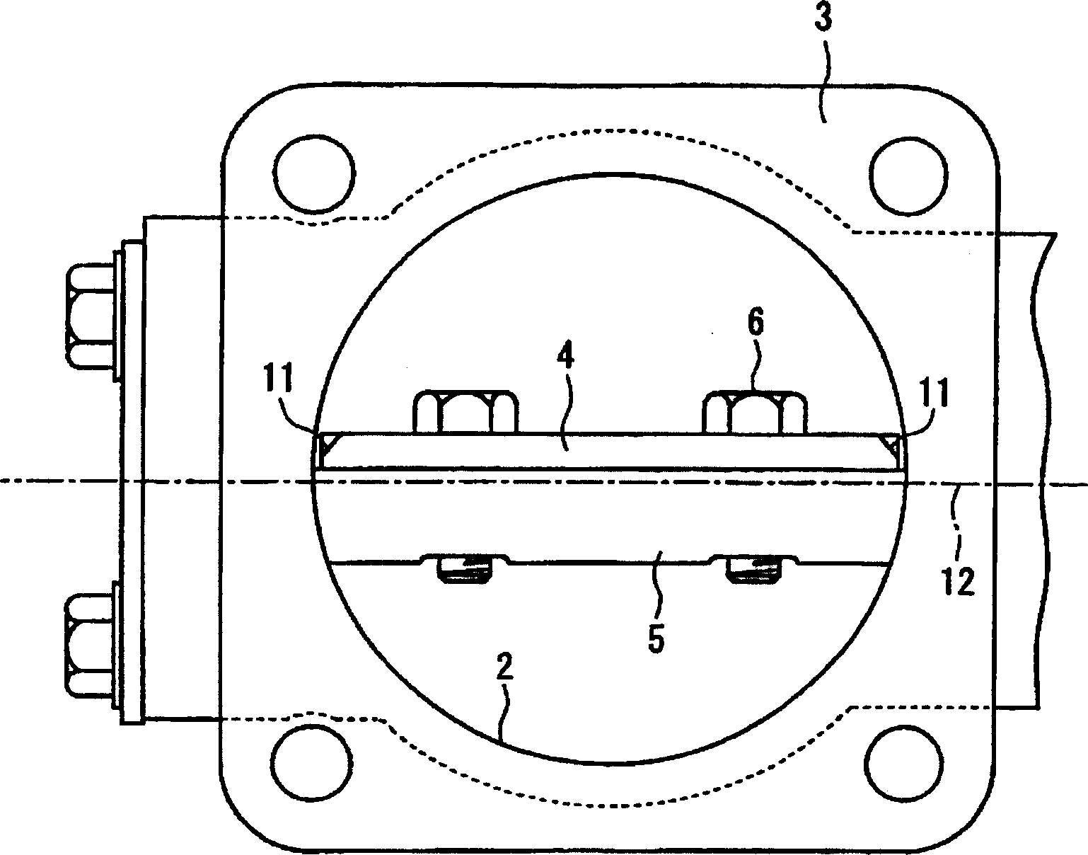
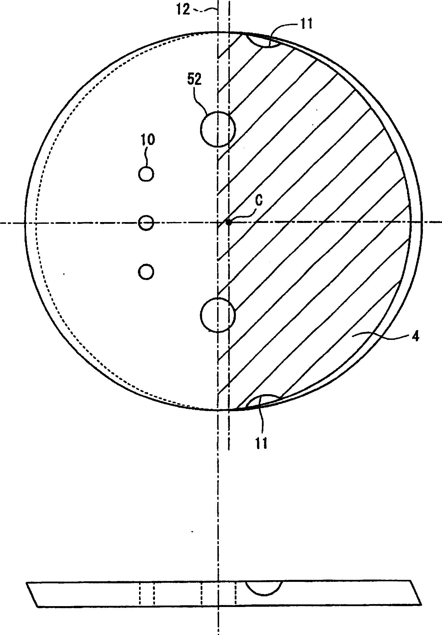
[0041] figure 1 , figure 2 The exhaust throttle valve of the present invention shown with Figure 7 Similarly, it is a butterfly valve provided in the valve body 3 forming the exhaust gas passage 2 . Install valve shaft 5 of valve body 4 also with Figure 7 The valve shaft has the same shape, has both ends embedded in the insertion hole 8 formed on the valve body 3, and a flat surface in the middle of the fixed valv...


PUM


Abstract

An exhaust gas throttle valve disposed in the exhaust system of an engine, wherein the center axis of rotation of a valve shaft (5) is set at a position deviated from the center axis of the exhaust gas passage, and two recessed portions (11) are symmetrically formed in the circumferential portion of a valve body (4) by cutting the surface thereof. The positions where the recessed portions (11) are formed are on the side of the center axis of the exhaust gas passage beyond the center axis (12) of rotation, and at where the peripheral portion of the valve body (4) faces the edge portions (9) where insertion holes (8) for the valve shaft (5) are opened in the exhaust gas passage. At these positions, the distance is a minimum between the peripheral portion of the valve body (4) and the edge portions (9). Therecessedportions (11) work to increase the gap relative to the edge portions (9) at that positions. It is therefore made possible to approximate the peripheral portion of the valve body (4) to the tubular wall of the exhaust gas passage (2) when the exhaust gas throttle valve is closed preventing the valve body (4) and the edge portions (9) from coming in contact together despite of the thermal expansion.

Description

technical field [0001] The present invention relates to a throttle valve installed downstream of an exhaust gas post-treatment device of a diesel engine, an exhaust brake valve for assisting braking force during deceleration of a vehicle, etc., and an exhaust throttle valve installed in an exhaust system of an engine Structure. Background technique [0002] As an important part of environmental measures, the regulation of harmful components in the exhaust gas of vehicle engines and the development of various technologies for reducing harmful components have put a lot of effort into it. In particular, regulations on diesel engines, particularly diesel engine exhaust gas, have been gradually strengthened in recent years, and there is a tendency for stricter regulations to be imposed in the future. Diesel engines, generally, are more thermally efficient than gasoline engines, although with carbon dioxide (CO 2 ) emissions, but there is still a strong demand to reduce particul...

Claims


Application Information

Patent Timeline
Patent Type & Authority Applications(China)
IPC IPC(8): B01D46/42F01N3/00F01N3/023F01N3/24F01N9/00F01N13/08F02D9/04F02D9/06F02D9/10
CPCF01N3/0231F01N3/106F01N3/0235F01N2260/10F01N13/0097F01N2013/026F01N2390/04F02D9/04F01N2430/085F01N2250/02F02D9/06F01N2390/00Y02T10/47F01N9/002Y02T10/40
Inventor 高桥英树
Owner ISUZU MOTORS LTD
Why Eureka
Try Eureka