
Generator system and method for operating such a system

A technology for generators and equipment, applied in the direction of control generators, motor generator control, electromechanical devices, etc., can solve the problems of expensive frequency converters, and achieve the effect of avoiding structural ventilation

Inactive Publication Date: 2005-10-12
ALSTOM TECH LTD
View PDF1 Cites 6 Cited by
  • Summary
  • Abstract
  • Description
  • Claims
  • Application Information

AI Technical Summary

Problems solved by technology

But the inverters used in such equipment are very expensive and also useless in the high-speed operation of the equipment

Method used


Image

  • Generator system and method for operating such a system
  • Generator system and method for operating such a system
  • Generator system and method for operating such a system

Examples


Embodiment Construction

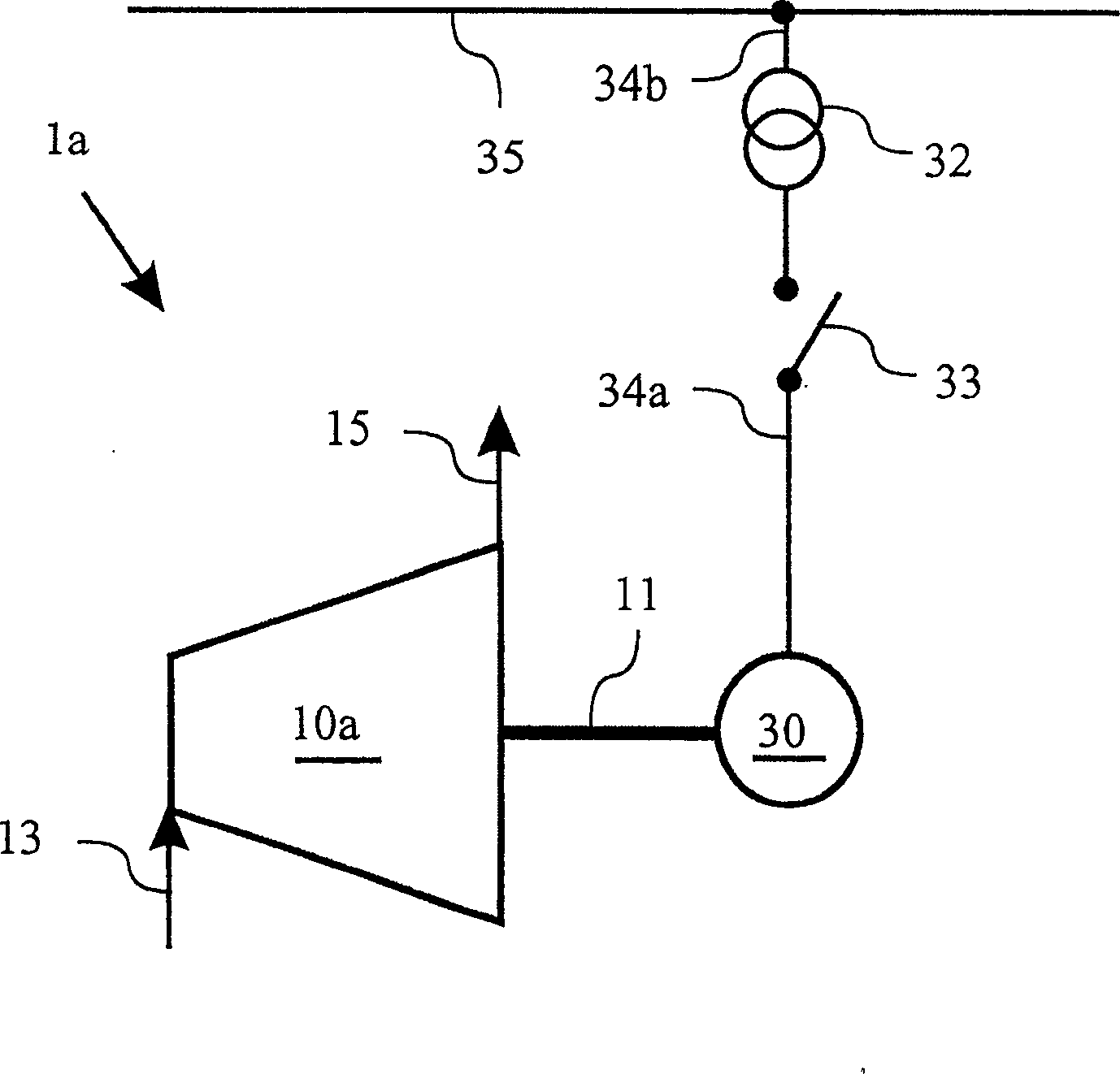
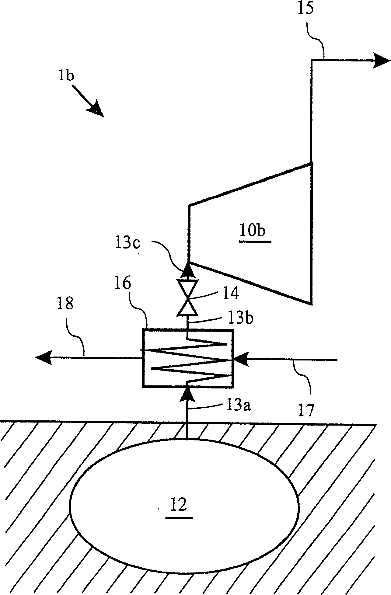
[0048] Figure 1a The principle represents the structure of a turbomachine installation 1a known from the prior art. The turbine system 1 a can be, for example, a steam turbine system or a CAES system.

[0049] The turbine system 1 a includes a turbine 10 a into which a through-fluid is introduced via an inlet line 13 . After passing through the turbine 10 a , the through-fluid is discharged at the outlet from the turbine 10 a via a discharge line 15 . The turbine 10 a shown here can be designed as an air turbine, a gas turbine, a steam turbine or also as a turbine embodied in another type. Depending on the type of turbine the through fluid is either air, a flue gas air mixture, steam or another fluid.

[0050] When flowing through the turbine 10a, the through-fluid expands to deliver work work, by means of which the rotor of the turbine 10a and the shaft 11 connected thereto are rotated. This rotation is translated into operation of the generator 30 via the shaft 11 . El...


PUM


Abstract

The invention relates to a generator system for generating an increased braking power, in particular during the startup and / or powering down of a turbine, drivingly connected to a generator, of a turbine system, e.g. a CAES system. The generator system includes the generator, which for generating current is drivingly connected to the turbine, and a transformer, which is connected on the primary side to the generator and on the secondary side to an external current network. A means for frequency adaptation is disposed between the generator and the transformer and is expediently embodied as capable of being put on line. By putting the means for frequency adaptation on line during the startup and / or the powering down of the turbine system, the turbine is acted upon by a greater braking power. In this way, the development of ventilation in the turbine can be largely avoided.

Description

technical field [0001] The invention relates to a generator installation which is driven by a turbine of a turbomachine installation, in particular a turbine of a CAES installation, for generating electric current. Furthermore, the invention relates to a method for operating such a generator installation, in particular during non-synchronous operation of the turbine. Background technique [0002] Modern turbine systems for generating electricity in combined power plants should be started from standstill to rated speed in the shortest possible time in order to ensure a high operational readiness of the system. This is particularly the case with turbine installations for peak loads. To meet such peaks, a compressed air energy storage system ("Compressed-Air-Energy-Storage"-System or CAES system for short) was provided at an early stage, which again places special demands on the start-up process according to its concept. [0003] The basic idea of ​​such a CAES system is to s...

Claims


Application Information

Patent Timeline
Patent Type & Authority Applications(China)
IPC IPC(8): H02H7/06H02K7/18H02K11/00H02P9/00H02P9/08H02P9/10H02P9/42H02P11/00
CPCH02P9/10H02P9/42
Inventor M·赫尔措格M·希格曼
Owner ALSTOM TECH LTD
Learn More