Acid washing device

A pickling equipment and pickling technology, applied in metal processing equipment, workpiece surface treatment equipment, manufacturing tools, etc., can solve the problems of reducing the quality of steel plates, reducing production efficiency, shortening the life of pickling solution, etc., to achieve high production efficiency, The effect of prolonging the maintenance cycle

Inactive Publication Date: 2005-10-19
PRIMETALS TECHNOLOGIES JAPAN LTD
View PDF1 Cites 3 Cited by
  • Summary
  • Abstract
  • Description
  • Claims
  • Application Information

AI Technical Summary

Problems solved by technology

In this gel-like SiO 2 In the case of particle removal, it is necessary to stop the operation of the equipment for a long time and perform cleaning of the equipment, etc., which has a great adverse effect on operation and maintenance, and also becomes a factor that reduces production efficiency.
[0011] However, in the above-mentioned conventional pickling equipment, no countermeasures have been taken against the particles generated in the pickling solution after pickling treatment and adversely affecting the operation of the equipment.
In addition, particles in the oxide scale suspended in the pickling solution shorten the life of the pickling solution and also cause a decrease in the quality of the steel sheet.

Method used


Image

  • Acid washing device
  • Acid washing device
  • Acid washing device

Examples


Embodiment 1

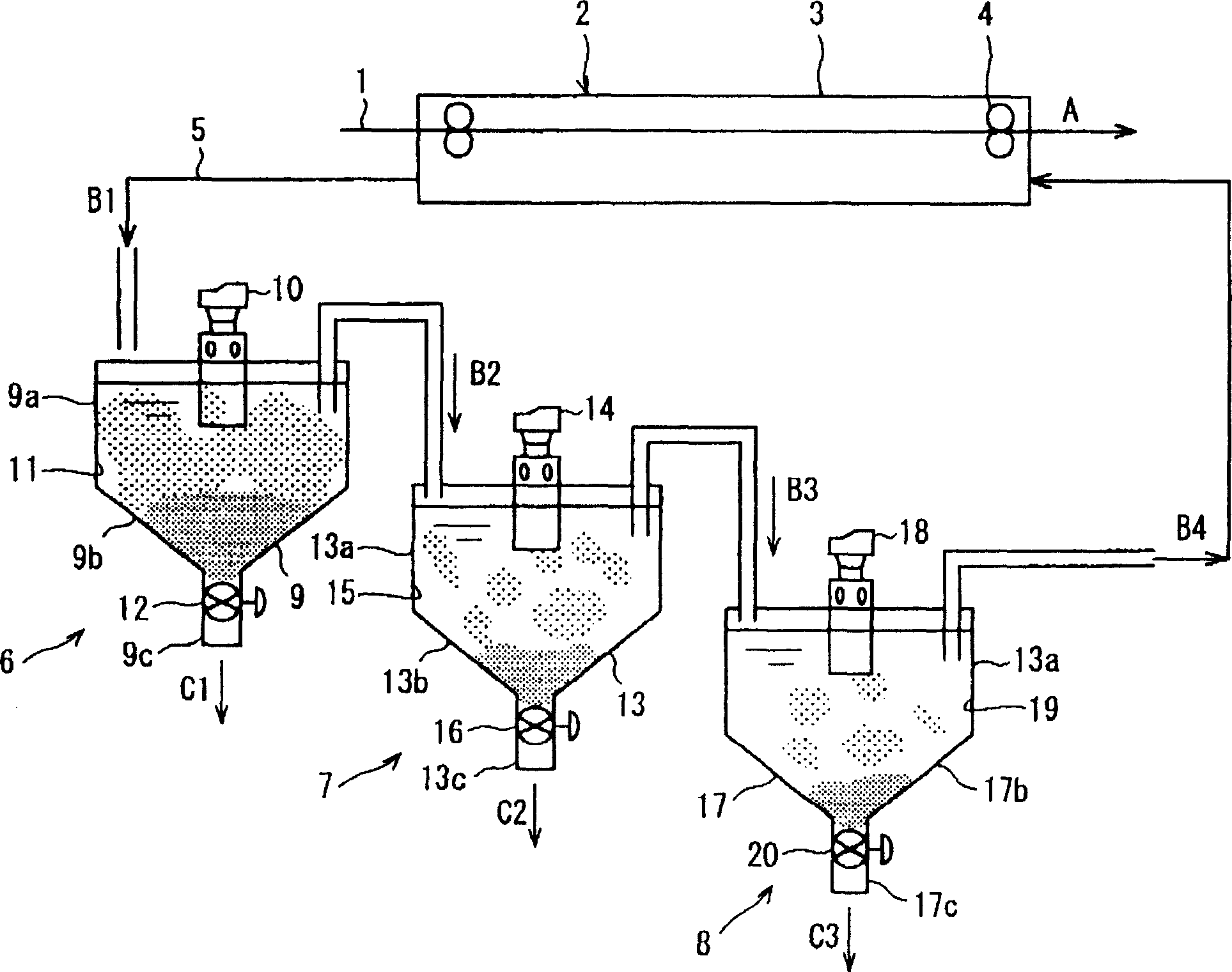
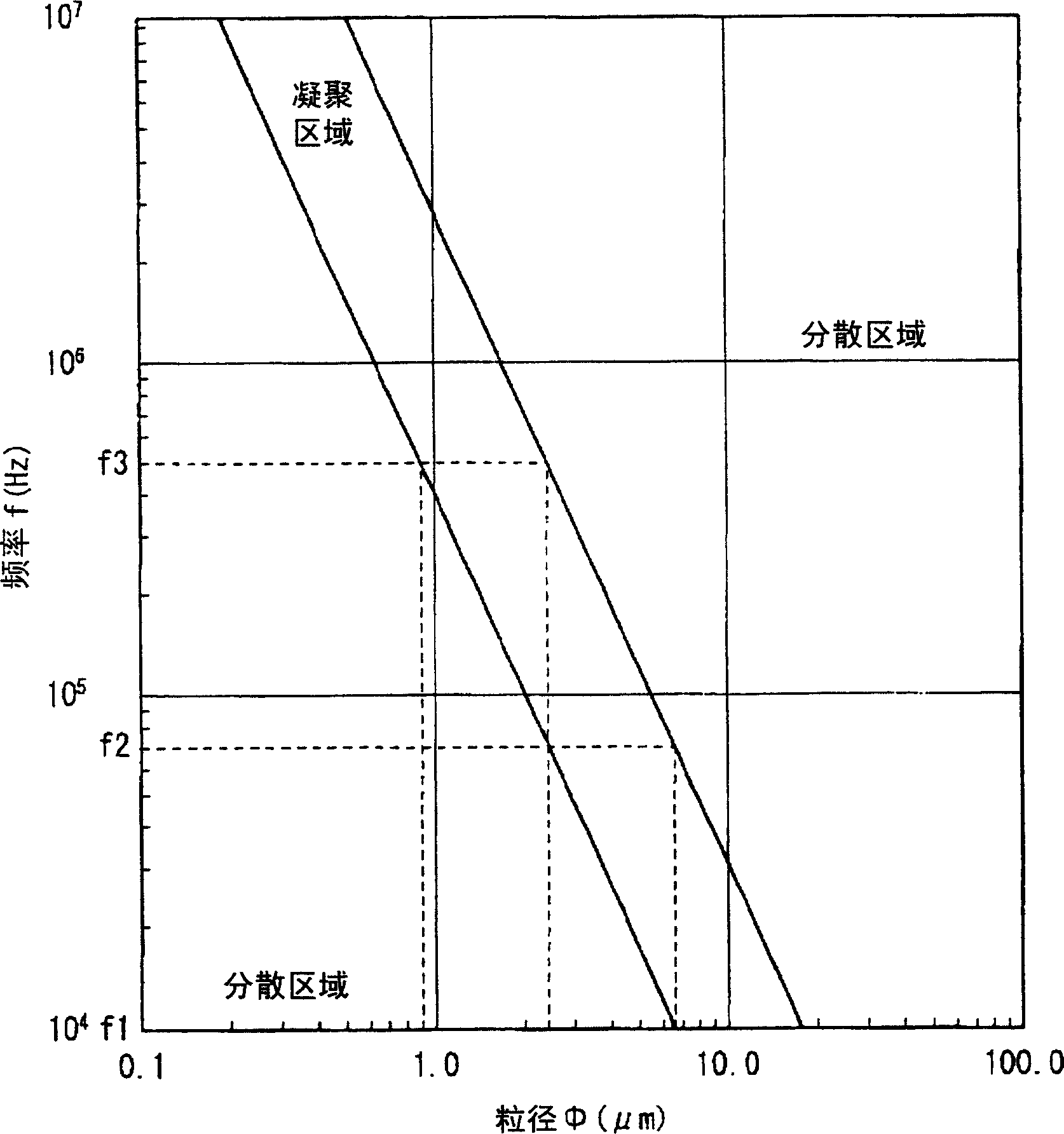
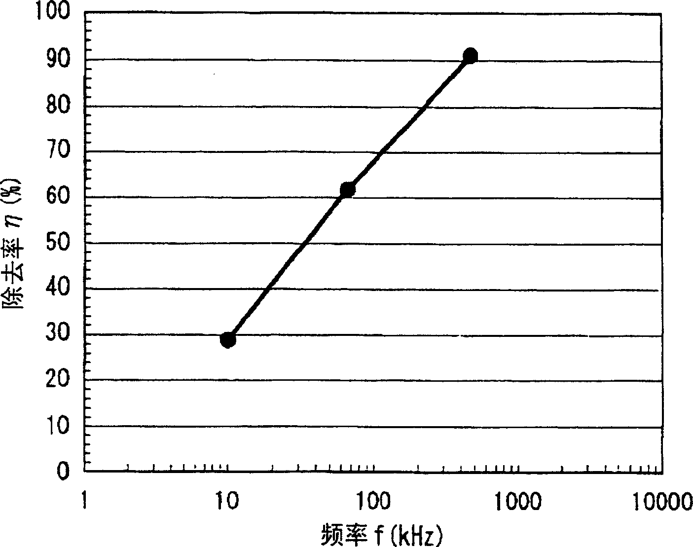
[0037] figure 1 It is a schematic diagram of the pickling facility of Example 1 of the present invention. figure 2 It is an aggregation and dispersion diagram showing the relationship between the ultrasonic frequency and the particle size of the microparticles. image 3 is the SiO in the pickling solution of Example 1 representing the present invention 2 A graph of particle removal rates.

[0038] Such as figure 1 As shown, the steel sheet 1 which is the steel sheet material containing silicon is supplied in the arrow direction A shown in the figure, and passes through the inside of the steel sheet pickling device 2 . The steel plate pickling device 2 includes a pickling tank 3 for storing pickling liquid for pickling the steel plate 1, and a drum 4 for cutting the pickling liquid. The pickling tank 3 communicates with a circulation path 5 for circulating a pickling liquid, and the pickling liquid flows in the circulation path 5 in a direction opposite to the supply direc...

Embodiment 2

[0064] Figure 4 It is a perspective view of the separation device of Example 2 of the present invention. Arrows B5 and B6 in the figure indicate the flow of pickling solution.

[0065] Figure 4 The separation device 21 shown is because it is described in the embodiment 1 figure 1 The separators 6 , 7 , and 8 disposed on the circulation path 5 of the pickling facility shown are changed and installed, so descriptions of the same symbols or symbols are omitted.

[0066] Separation device 21 is equipped with for separating SiO from pickling solution 2 The separation tank 22 for particles, the ultrasonic vibrator 23 that emits an ultrasonic wave with a frequency f1 immersed in the pickling solution stored in the separation tank 22, the ultrasonic vibrator 24 that emits an ultrasonic wave with a frequency f2, and the ultrasonic vibrator that emits an ultrasonic wave with a frequency f3 25 and reflection plates 26, 27, 28 provided so as to face these ultrasonic vibrators 23, 24...


PUM


Abstract

The pickling equipment equipped with a pickling tank 3 for performing pickling of the steel sheet 1 containing silicon by successively passing the steel sheet 1 and a circulating route 5 for circulating the pickling solution in the pickling tank 3 is provided with ultrasonic vibrator transducers 10, 14 and 18 which oscillate ultrasonic waves of different frequencies f 1, f 2, and f 3 to the pickling solution circulating in the circulating route at separation tanks 9, 13 and 17 such that the SiO2particles of the grain sizes different from each other of the respective frequencies f 1, f 2, an f 3 are removed by flocculation and settlement. Thus, SiO2particles in a pickling solution generated during pickling of various silicon steel sheets can be decreased, and long-term operation and the period of maintenance work can be prolonged and productivity is high.

Description

technical field [0001] The invention relates to a pickling equipment for pickling steel plates by recycling pickling liquid. Background technique [0002] In the manufacturing process of the steel plate, the steel plate after hot rolling or the like is once coiled, cooled outdoors or the like, and then unrolled for cold rolling or the like. In this cooling step, scales are formed as oxides on the surface of the steel sheet. Therefore, pickling treatment is performed in order to remove this scale before cold rolling or the like. The so-called pickling treatment refers to the chemical reaction of the oxide scale formed on the surface of the steel plate, such as cold-rolled steel plate or hot-rolled steel plate, with pickling solutions such as hydrochloric acid or nitric acid, and removes the oxide scale. processing. The pickling facility in the manufacturing process of the steel plate is installed to perform the pickling treatment. [0003] The conventional pickling method...

Claims


Application Information

Patent Timeline
Patent Type & Authority Applications(China)
IPC IPC(8): C23G3/02B21B45/02C23G1/08C23G1/36
CPCC23G1/36C23G3/027B21B45/0287C23G1/08C23G3/02C23G3/021C23G3/025
Inventor 马场幸雄饭田静男坂本润大田利行
Owner PRIMETALS TECHNOLOGIES JAPAN LTD
Why Eureka
Try Eureka