
Imaging apparatus

a technology of imaging apparatus and battery, which is applied in the field of imaging apparatus, can solve the problems of not being able to supply the required amount of current from the battery, still many problems to be solved, and portable apparatus such as a digital camera driven with a battery has a limitation on the current to be supplied there, so as to save power consumption and long-term operation

Inactive Publication Date: 2011-06-02
OHSUGA JUN +2
View PDF31 Cites 14 Cited by
  • Summary
  • Abstract
  • Description
  • Claims
  • Application Information

AI Technical Summary

Benefits of technology

[0012]An object of the present invention is to provide an imaging apparatus which employs a semiconductor light-emitting device as a strobe light, and which is capable of a long-time operation by saving power consumption without causing a current consumption peak when the strobe light employing a semiconductor light-emitting device is used.
[0014]In addition, according to an embodiment of the present invention to achieve the forgoing object, an imaging apparatus having a plurality of semiconductor light-emitting devices functioning as a strobe light includes a light emitting device controlling unit for controlling the number of semiconductor light-emitting devices to emit light among the plurality of semiconductor light-emitting devices. The light emitting device controlling unit controls the number of semiconductor light-emitting devices to emit light under a predetermined condition for increasing a current consumption amount.
[0019]Furthermore, according to an embodiment of the present invention to achieve the foregoing object, an imaging apparatus includes: an imaging unit for picking up an image of a subject with a solid state imaging device; a lighting unit for lighting a subject; a controlling unit for controlling an operation of each of the imaging unit and the lighting unit; and a power supply unit for supplying power to at least the imaging unit, the lighting unit and the controlling unit. The controlling unit controls a change of a load on the lighting unit in order to prevent deterioration of image quality of an image obtained by the imaging unit.

Problems solved by technology

As such, there are still many problems to be solved in order to put the LEDs of three colors into practical use as a strobe light.
In particular, a portable apparatus such as a digital camera driven with a battery has a limitation on current to be supplied thereto.
Accordingly, even when an apparatus requires an amount of current larger than that of a battery supply current, the required amount of current cannot be supplied from the battery to the apparatus, which may stop all the operations in the apparatus, as a whole.
In addition, when the current consumption becomes large as described above, that is, when a large load is applied to a power source, the voltage of the power source shifts due to the load change.
This results in deterioration of image quality, and also leads to even a failure in obtaining an image, itself, in the worst case.
However, in the conventional technique disclosed in Japanese Patent Application laid-open Publication No. 2001-215579 (called Patent Document 2), it is considered that light is flashed in synchronization with a timing of imaging in a case where an image is taken by using a semiconductor light-emitting device or a lighting unit such as a lamp, but the aforementioned problems are not considered.

Method used


Image

  • Imaging apparatus
  • Imaging apparatus
  • Imaging apparatus

Examples


first embodiment

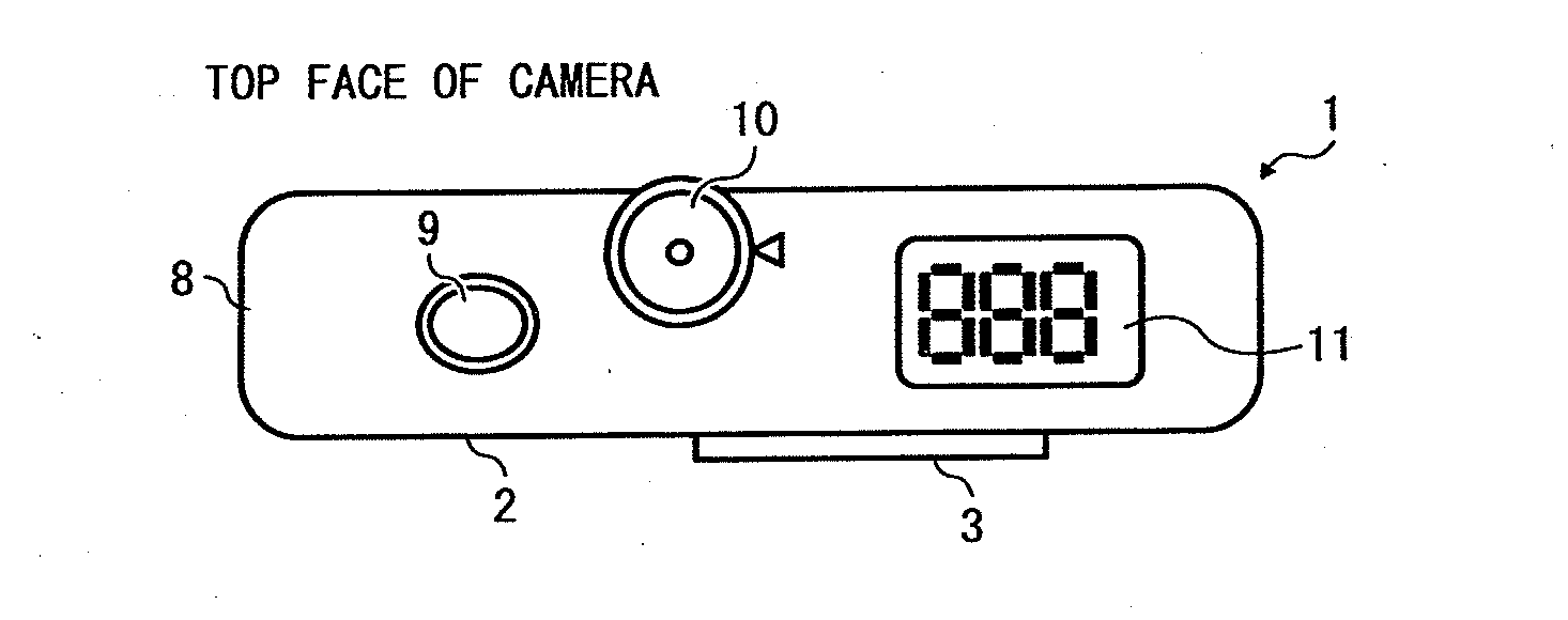
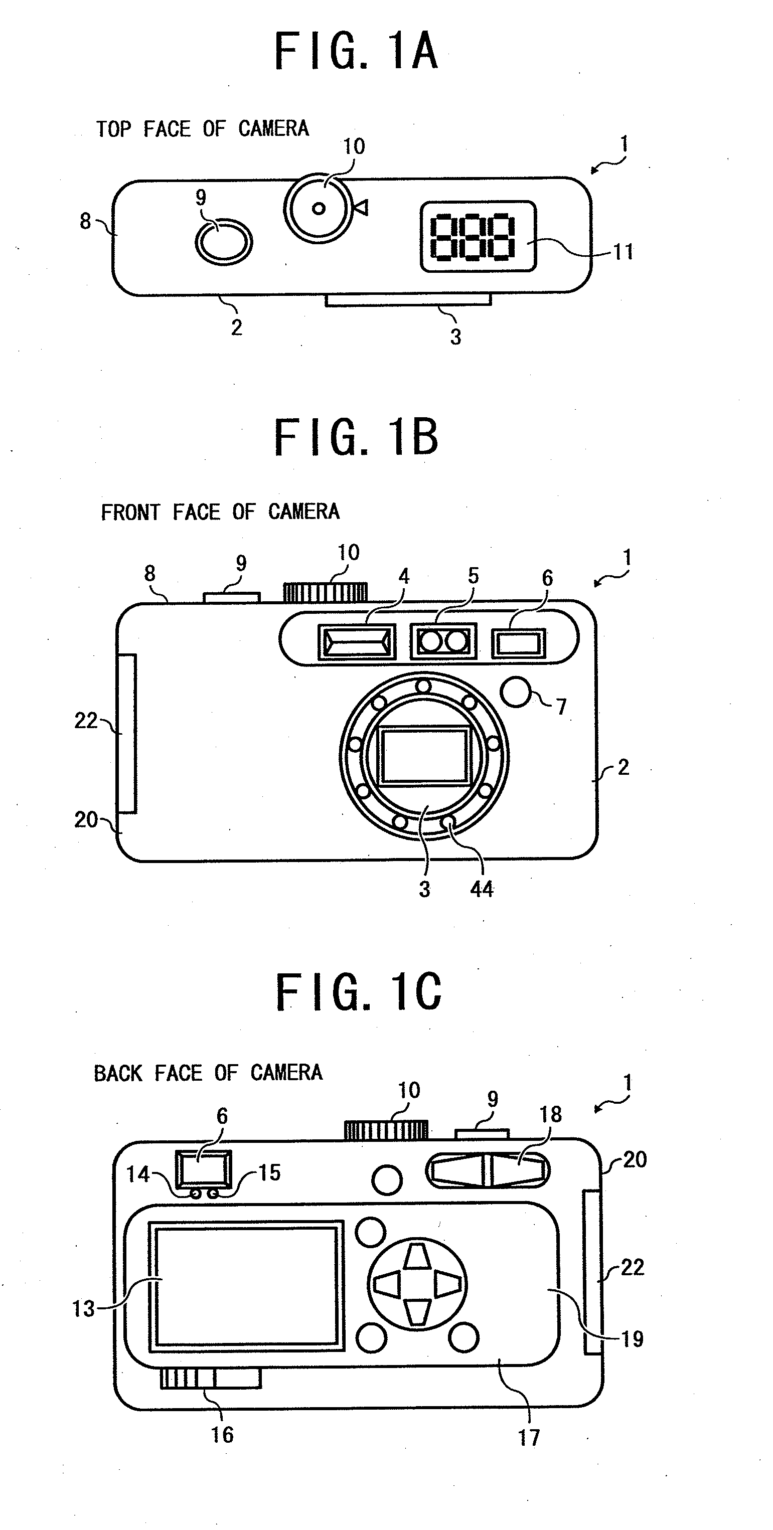
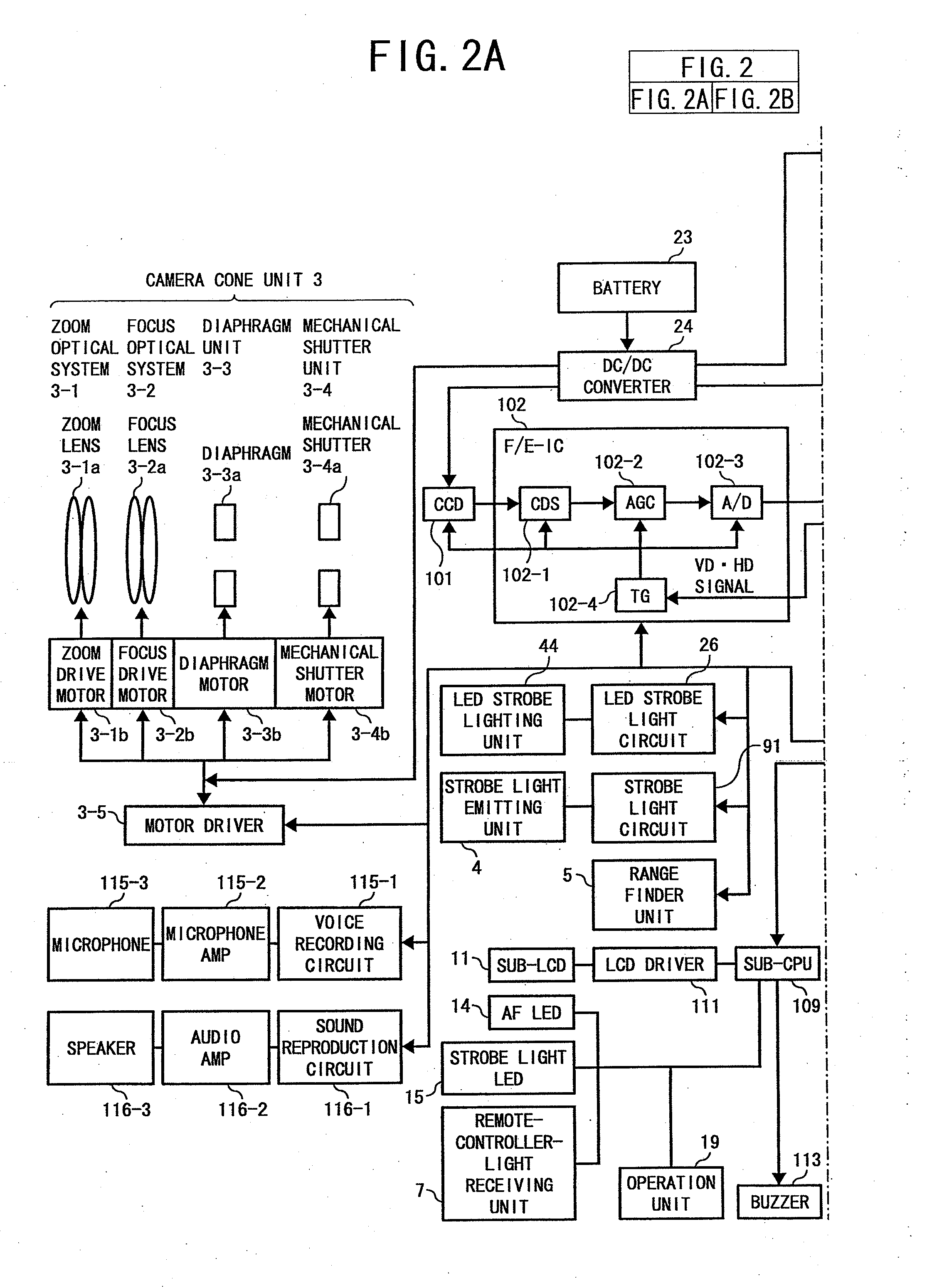
[0083]Hereinafter, descriptions will be provided for a first embodiment of the digital camera 1 configured as described above.

[0084]Firstly, a general sequence of recording moving images will be described. This embodiment shows an example of the digital camera 1 at a time of recording moving images, for the purpose of showing that the digital camera 1 according to this embodiment more surely produces an effect when using the LED strobe lighting unit 44 while recording moving images. However, the application of the present invention is not limited to a time of recording moving images, and the present invention can be also used at a time of picking up a still image.

[0085]FIG. 3 is a flowchart showing the general sequence of recording moving images. FIG. 4 is a diagram showing a timing chart at the recording time. The sequence of recording moving images with the digital camera 1 of this embodiment will be described by referring to FIG. 3. When the digital camera 1 of this embodiment re...

second embodiment

[0108]Hereinafter, a second embodiment of the imaging apparatus of the present invention will be described.

[0109]In general, a primary battery such as an alkaline battery, a nickel-manganese battery and a lithium battery, and a secondary battery such as a nickel hydride battery and a lithium-ion battery have been heretofore used as batteries for a digital camera. The progress in developing batteries has increased the capacity of a battery year by year. Thereby, a longer battery life has been achieved. Meanwhile, the improvement of semiconductor technology leads to the development of an IC capable of operating with a lower voltage. With this IC, a battery can be used even after the battery starts supplying a lower voltage than a conventional battery, whereby a much longer battery life can be achieved. The functions of a digital camera in recent years have been diversified, so that the digital camera has not only a still image pickup function, but also a moving image recording functio...

third embodiment

[0129]Hereinafter, a third embodiment of the present invention will be described. As a generally-used battery for a conventional digital camera, there have been primary batteries such as an alkaline battery, a nickel-manganese battery and a lithium battery and secondary batteries such as a nickel hydride battery and a lithium ion battery. The progress of developing a battery has increased the battery capacity, whereby battery life has been attempted to be made much longer. In addition, the improvement of the semiconductor technology has led to the development of an IC capable of operating with a low voltage. Since use of this IC allows a battery to be used even after the battery starts supplying a lower voltage than a conventional battery, a much longer battery life can be achieved. The alkaline battery of the primary battery and the nickel hydride battery of the secondary battery are identical to each other in shape, and are substantially equal to each other in the voltage range. A...


PUM


Abstract

An imaging apparatus includes a semiconductor light-emitting device functioning as a strobe light having a current limitation unit for limiting current to flow to the semiconductor light-emitting device. The current limitation unit limits current to flow to the semiconductor light-emitting device under a predetermined condition for increasing a current consumption amount.

Description

CROSS-REFERENCE TO RELATED APPLICATIONS[0001]This application is a divisional of U.S. patent application Ser. No. 11 / 855,946, filed on Sep. 14, 2007, the subject matter of which is incorporated in its entirety by reference herein.PRIORITY CLAIM[0002]The present application is based on and claims priority from Japanese Application Number 2006-251941, filed on Sep. 15, 2006, the disclosure of which is hereby incorporated by reference herein in its entirety.BACKGROUND OF THE INVENTION[0003]1. Field of the Invention[0004]The present invention relates to an imaging apparatus such as a digital camera which takes and reproduces electronic images.[0005]2. Description of Related Art[0006]In a general strobe light device used for a camera, electric charges are stored in a capacitor, and a xenon tube is caused to emit light in accordance with a light emission control signal. Meanwhile, in recent years, semiconductor light-emitting devices such as a white LED and superluminescent LEDs of R, G a...

Claims


Application Information

Patent Timeline
Patent Type & Authority Applications(United States)
IPC IPC(8): H04N5/225
CPCH04N5/232H04N5/2354H04N5/23241H04N23/651H04N23/74
Inventor OHSUGA, JUNYOSHIDA, KAZUHIROSERIKAWA, YOSHIO
Owner OHSUGA JUN
Learn More