Calibration of a level gauge system

a level gauge and level gauge technology, applied in the direction of transmission systems, liquid/fluent solid measurement, engine lubrication, etc., can solve the problems of insufficient resolution of conventional samplers, complex and relatively expensive process design, and lack of temperature-stable clock referen

Active Publication Date: 2015-05-19
ROSEMOUNT TANK RADAR
View PDF14 Cites 3 Cited by
  • Summary
  • Abstract
  • Description
  • Claims
  • Application Information

AI Technical Summary

Benefits of technology

[0015]The present invention is based on the realization that the timing synchronization in the wireless communication network can be used to calibrate a level gauge system if time stamp signals are generated based on the wireless communication network timing synchronization, and the number of sampling periods between time stamp signals is registered. From an accurate time and the number of sampling periods, the (average) sampling period can readily be estimated. Using this estimated sampling period, and the sampled reflection signal from the tank, the filling level can be determined with high accuracy without the need for a very accurate and stable clock reference in the level gauge system.
[0016]Accordingly, various embodiments of the present invention provide for high accurate determination of the filling level in a tank without the need for a temperature stable and highly accurate clock reference in the level gauge system. As a consequence, the power consumption of the level gauge system can be kept sufficiently low to provide for long time operation of the level gauge system while maintaining the desired measurement accuracy (in the order of mm). In the case of a battery-powered level gauge system, accurate determination of the filling level should be possible to provide for more than 5 years on a single battery pack.

Problems solved by technology

Conventional samplers are not fast enough to capture such a fast pulse with sufficient resolution to detect a distance with high accuracy.
While providing a satisfactory result, this process requires a complex and relatively expensive design.
A potential problem with sampling a signal in real time using a series of on-chip elements is the absence of a temperature-stable clock reference.
For example, the transceiver module may exhibit a large temperature drift, since all delay elements in the chip possess pronounced temperature dependence.

Method used


Image

  • Calibration of a level gauge system
  • Calibration of a level gauge system
  • Calibration of a level gauge system

Examples


Embodiment Construction

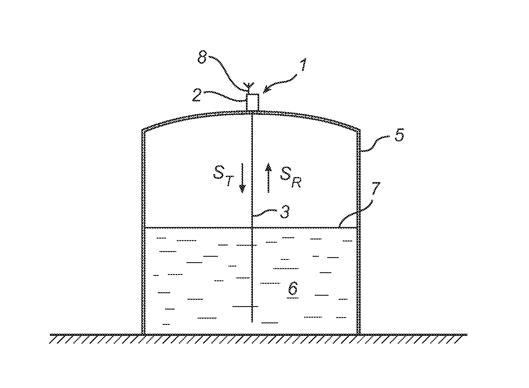
[0045]The present invention will herein be described with reference to a level gauge device of the so-called GWR (Guide Wave Radar) type in which the electromagnetic signals are guided back and forth between the measuring unit of the level gauge and the product to be gauged by a transmission line probe. However, this is by no means to be considered a limitation of the present invention, which may also advantageously be used for non-contact level gauge systems, in which electromagnetic waves are radiated towards the product in the tank using a radiating antenna.

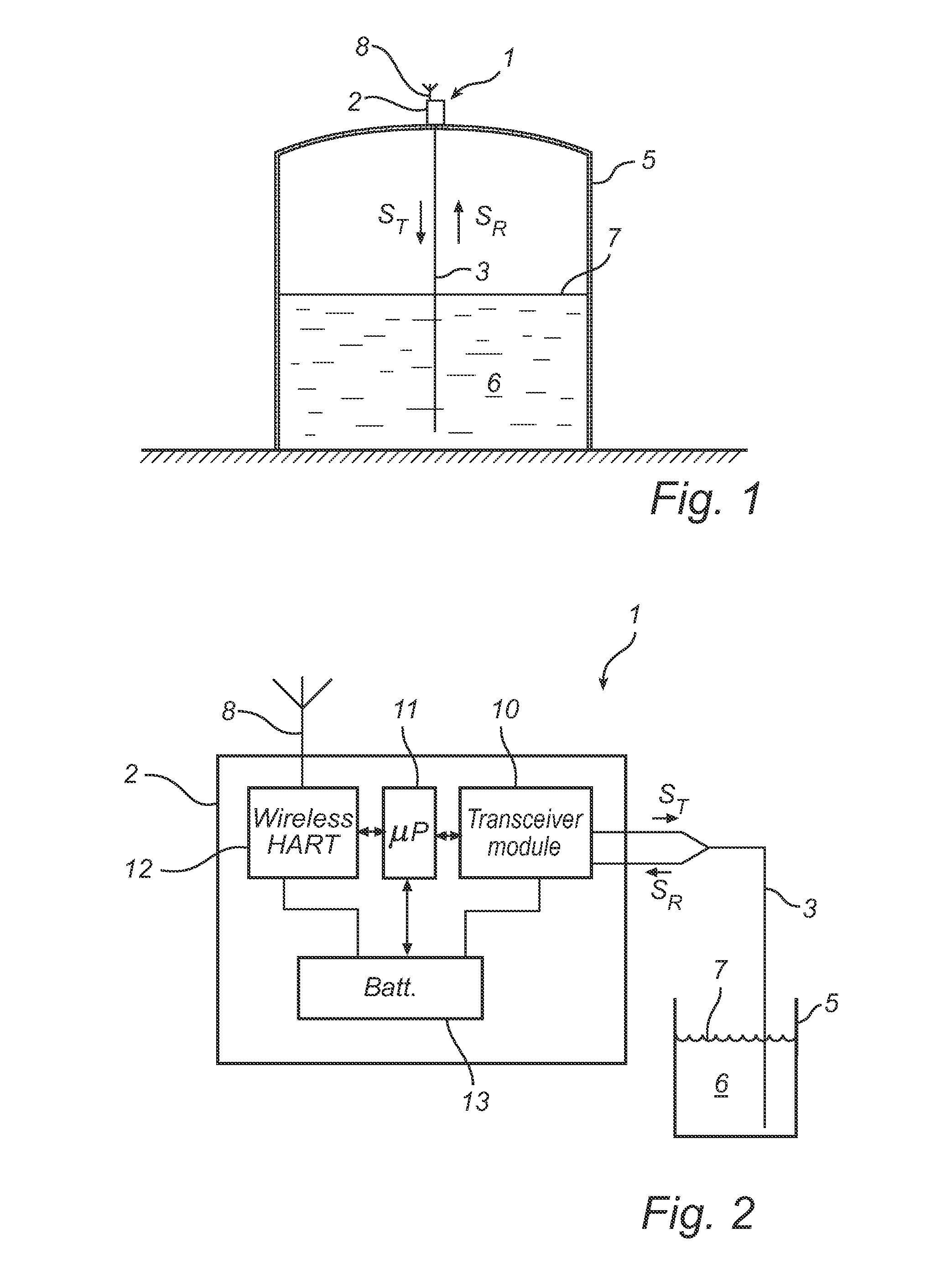
[0046]FIG. 1 schematically illustrates a level gauge system 1 according to an embodiment of the present invention, comprising a measurement electronics unit 2, and a signal propagation device in the form of a transmission line probe 3. The radar level gauge system 1 is provided on a tank 5, which is partly filled with a product 6 to be gauged. By analyzing a measuring signal ST being guided by the transmission line probe 3 tow...


PUM


Abstract

A method of calibrating a level gauge system using electromagnetic signals to determine a filling level of a product in a tank. The level gauge system comprises a real time sampler for sampling a reflection signal with a sampling period between consecutive samples. The method comprises the steps of: receiving timing signals from a wireless communication network; generating time stamp signals based on the timing signals; registering a number of the sampling periods between a first time stamp signal and a second time stamp signal; and determining the sampling period based on the registered number of sampling periods and a time between the first time stamp signal and the second time stamp signal. Various embodiments of the present invention provide for high accurate determination of the filling level in a tank without the need for a temperature stable and highly accurate clock reference in the level gauge system.

Description

TECHNICAL FIELD OF THE INVENTION[0001]The present invention relates to calibration of a level gauge system and to a level gauge system with calibration capabilities.TECHNICAL BACKGROUND[0002]A distance measurement device, or ranging device, is based on the principle that an electromagnetic signal is transmitted towards a surface or an object, and a reflected signal is received. The distance can then be determined based on the time-of-flight of the signal to the surface or object and back. This determination can be performed using suitable signal processing. Ideally, the received signal would simply be sampled in order to detect an echo peak. However, as electromagnetic waves propagate with the speed of light, the echo peak will typically have a duration in the order of only a few nanoseconds. Conventional samplers are not fast enough to capture such a fast pulse with sufficient resolution to detect a distance with high accuracy.[0003]Solutions to this problem are known, for example ...

Claims


Application Information

Patent Timeline
Patent Type & Authority Patents(United States)
IPC IPC(8): G01J5/02G01F23/284G01F25/00
CPCG01F23/284G01F25/0061G01F25/20
Inventor WENGER, FABIANNORDLUND, MATSHAGG, LENNART
Owner ROSEMOUNT TANK RADAR
Why Eureka
Try Eureka