Directly driving screw pump device

A technology for driving screw and pump devices, which is applied in the direction of pumps, axial flow pumps, non-variable pumps, etc. It can solve the problems of damage to the reduction box, mechanical loss, and large volume, so as to eliminate oil leakage and reduce oil production costs. , the effect of reducing the volume

Inactive Publication Date: 2005-10-19
胜利油田胜利电器有限责任公司
View PDF0 Cites 18 Cited by
  • Summary
  • Abstract
  • Description
  • Claims
  • Application Information

AI Technical Summary

Problems solved by technology

This structure has three major defects: first, there is mechanical loss in the belt drive and gear reduction box, which generally accounts for about 15% of the shaft power of the screw pump; In addition to the belt drive, the driving gear of this structure is on one side. When the polished rod requires a large torque (for example, the torque exceeds 1500N·m), the unilateral transmission gear will generate side torque in the reduction box, and excessive side torque Will damage the gear box
In addition, the existing screw pump oil production equipment has large volume and heavy weight.

Method used


Image

  • Directly driving screw pump device

Examples


Embodiment Construction

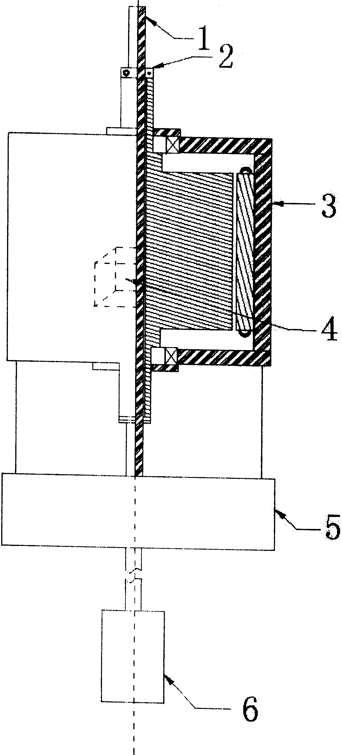
[0010] As shown in Figure 1, the fixed seat 5 is the basic installation base, the low-speed motor 3 is installed on the fixed seat 5, the motor controller is directly installed inside the low-speed motor 3, and the output line of the motor controller is connected to the incoming line of the low-speed motor 3 , the incoming line of the motor controller is connected to the power grid. The polished rod 1 passes through the hollow shaft of the low-speed motor 3 and the center of the fixing seat 5. The polished rod 1 is fixedly connected with the hollow shaft of the low-speed motor 3 through the coupling 2. Connected with the output shaft of the low-speed motor 3, the screw pump body 6 is at the lowest end of the device.

[0011] The rotating shaft of the low-speed motor 3 is a hollow structure, and is vertically placed on the holder 5 . The motor controller is used in conjunction with the low-speed motor 3, and the low-speed motor 3 outputs a lower speed under the control of the ...


PUM


Abstract

The directly driven screw pump device consists of polished rod, shaft coupler, low speed motor, motor controller, fixing seat and screw pump body. It features the hollow low speed motor shaft penetrating through the polished rod to connect integrally with the polished rod; the polished rod penetrating through the central hole in the fixing seat to connect to the shaft of screw pump in well; the low speed motor fixed on the fixing seat; the fixing seat fixed on the well head through support; and coaxiality of the polished rod, the low speed motor and the fixing seat with the well head.

Description

1. Technical field [0001] The invention relates to an oil production equipment, in particular to a direct-driven screw pump device. 2. Background technology [0002] In the existing screw pump oil production equipment, the power system of the screw pump is driven by an ordinary asynchronous motor through a belt to drive the bevel gear reducer, and finally the reducer drives the long rod of the screw pump in the well. This structure has three major defects: first, there is mechanical loss in the belt drive and gear reduction box, which generally accounts for about 15% of the shaft power of the screw pump; In addition to the belt drive, the driving gear of this structure is on one side. When the polished rod requires a large torque (for example, the torque exceeds 1500N·m), the unilateral transmission gear will generate side torque in the reduction box, and excessive side torque Will damage the gear box. In addition, the existing screw pump oil production equipment has large...

Claims


Application Information

Patent Timeline
Patent Type & Authority Applications(China)
IPC IPC(8): E21B43/00F04B47/02F04D3/02
Inventor 丛恒利唐永建马景波朱星波张森
Owner 胜利油田胜利电器有限责任公司
Why Eureka
Try Eureka