Magnetic spring induction type reciprocating motion counter

A reciprocating motion, reed sensor technology, used in engine components, engine lubrication, lubricating parts, etc., can solve problems such as the oil supply at the lubrication point being lower than the design value, the machining error of the connecting rod, and the assembly error of the piston rod. Achieve the effect of improving convenience, fewer assembly parts, and avoiding dynamic seal design

Inactive Publication Date: 2018-11-20
QINGDAO TECHNOLOGICAL UNIVERSITY +1
View PDF6 Cites 0 Cited by
  • Summary
  • Abstract
  • Description
  • Claims
  • Application Information

AI Technical Summary

Problems solved by technology

In the prior art, the connecting rod of the sealing ring-type progressive oil distributor is connected to the piston rod, and the housing is connected to the housing of the progressive oil distributor. The connecting rod reciprocates with the piston rod and is counted by the proximity sensor. The connecting rod is sealed by a sealing ring to ensure that the high-pressure lubricant in the progressive oil distributor will not leak, but the inner cavity of the housing cannot withstand high-pressure oil. Due to the high oil pressure in the progressive oil distributor, the viscosity of the lubricating oil High, the assembly error of the piston rod, the processing error of the connecting rod, and the wear and tear of the reciprocating movement of the connecting rod cause the sealing ring to often leak oil. Once the oil leakage of the sealing ring will cause the oil supply of the lubrication point to be lower than the design value, resulting in Inaccurate, pollutes the working environment at the same time, and has poor practicability; therefore, a magnetic spring induction reciprocating counter is designed and prepared. The counter has a long life, accurate counting, and can realize precise oil supply

Method used


Image

  • Magnetic spring induction type reciprocating motion counter
  • Magnetic spring induction type reciprocating motion counter
  • Magnetic spring induction type reciprocating motion counter

Examples


Embodiment 1

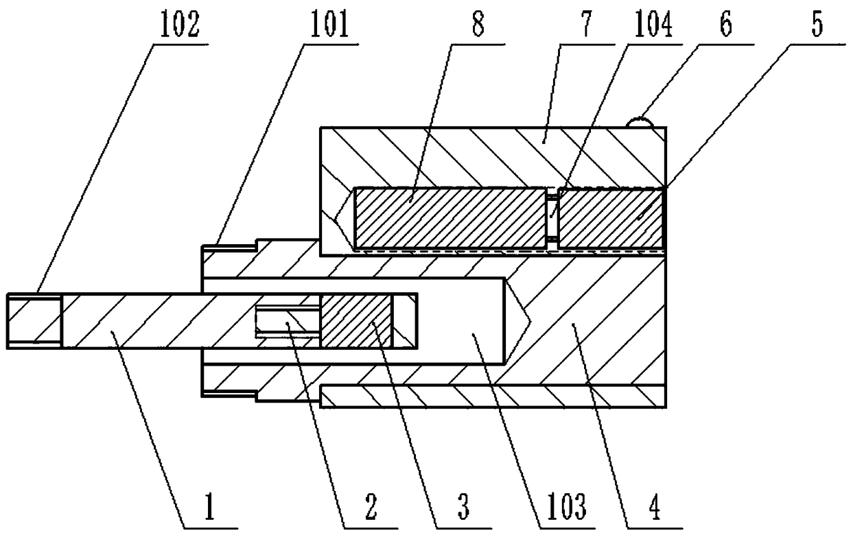
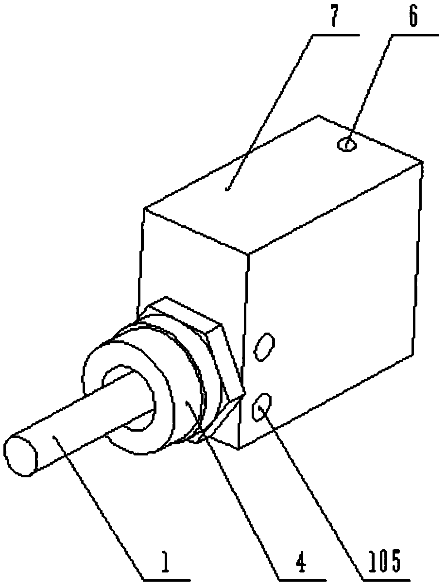
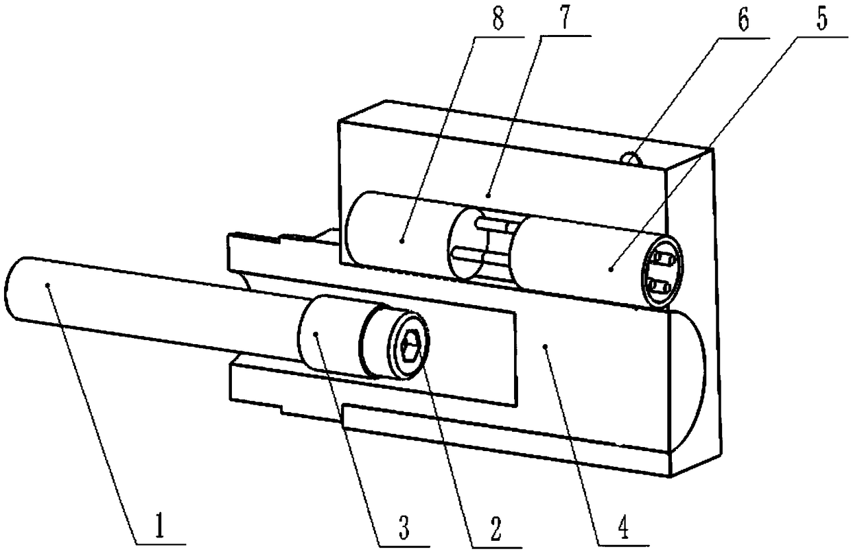
[0019] The main structure of the magnetic reed induction type reciprocating motion counter described in this embodiment includes a connecting rod 1, a bolt 2, a ring magnet 3, a connecting sleeve 4, an aviation plug 5, an indicator light 6, a casing 7, a magnetic reed sensor 8, a connecting sleeve External thread 101, connecting rod external thread 102, connecting sleeve cavity 103, reed sensor mounting hole 104, housing fixing thread 105, housing connecting sleeve mounting hole 106;

[0020] The left end of the cylindrical connecting rod 1 is connected with the piston rod in the progressive distributor, and the right end of the connecting rod is covered with a ring magnet 3, which is arranged on the right side of the ring magnet 3 to support and prevent the ring magnet 3 from connecting rod 1. Bolt 2 that slides down, the ring magnet 3 can reciprocate with the piston rod in the progressive oil volume distributor, the upper part of the ring magnet 3 is provided with a reed sens...


PUM


Abstract

The invention belongs to the field of oil and gas lubricating equipment, and relates to a magnetic spring induction type reciprocating motion counter. The counter is used in a progressive oil quantitydistributor. The main structure of the counter comprises a connecting rod, a connecting sleeve, an annular magnet, a bolt, a shell, an aviation plug, an indicating lamp and a magnetic spring sensor,the connecting sleeve is arranged on a progressive distributor shell, the inner cavity of the connecting sleeve communicates with an inner cavity of a piston rod of the progressive distributor, the connecting rod is arranged in the connecting sleeve, one end of the connecting rod is connected with the piston rod of the progressive distributor, the other end of the connecting rod is provided with the annular magnet, moreover, the annular magnet is fixed by a bolt, and the annular magnet and the piston rod of the progressive distributor do reciprocating motion together. A shell is arranged outside the connecting sleeve, an inner hole is formed in the upper side of the shell, the magnetic spring sensor is arranged in the inner hole, the magnetic spring sensor is used for recording the reciprocating motion frequency of the annular magnet in the using process, so that the oil supply quantity is controlled, the reliability of signal transmission is improved, dynamic sealing design is avoided, and the problem of oil leakage caused by abrasion of a sealing part is eliminated.

Description

Technical field: [0001] The invention belongs to the technical field of oil-air lubrication equipment, and relates to a counter design of a progressive oil volume distributor, in particular to a magnetic spring induction type reciprocating motion counter. Background technique: [0002] The progressive oil volume distributor is a key component in the oil-air lubrication system. The progressive oil volume distributor can output the lubricating oil of a single oil circuit input by the oil pump from multiple oil circuit outlets in sequence, and control the amount of lubricating oil. Metering the output of the oil-air lubrication system is the basis for realizing multi-point and quantitative oil supply in the oil-air lubrication system. The progressive oil distributor is driven by pressure oil, through the logical action of the internal plunger pump, it realizes the sequential output of multi-channel lubricating oil, and at the same time records the number of reciprocating moveme...

Claims


Application Information

Patent Timeline
Patent Type & Authority Applications(China)
IPC IPC(8): F16N25/02F16N29/00
Inventor 张磊郭峰刘牧原彭淑玲王希
Owner QINGDAO TECHNOLOGICAL UNIVERSITY
Why Eureka
Try Eureka