Mechanical damper for air pad instability

A mechanical damping and mechanical technology, which is applied in the field of medical imaging, can solve the problems of large space and bulkiness, and achieve the effects of reducing wear, reducing noise and increasing rotational potential energy

Inactive Publication Date: 2005-10-19
KONINK PHILIPS ELECTRONICS NV
View PDF0 Cites 1 Cited by
  • Summary
  • Abstract
  • Description
  • Claims
  • Application Information

AI Technical Summary

Problems solved by technology

This is a bulky design that requires a lot of space and may not be feasible in narrow bench systems

Method used


Image

  • Mechanical damper for air pad instability
  • Mechanical damper for air pad instability
  • Mechanical damper for air pad instability

Examples


Embodiment Construction

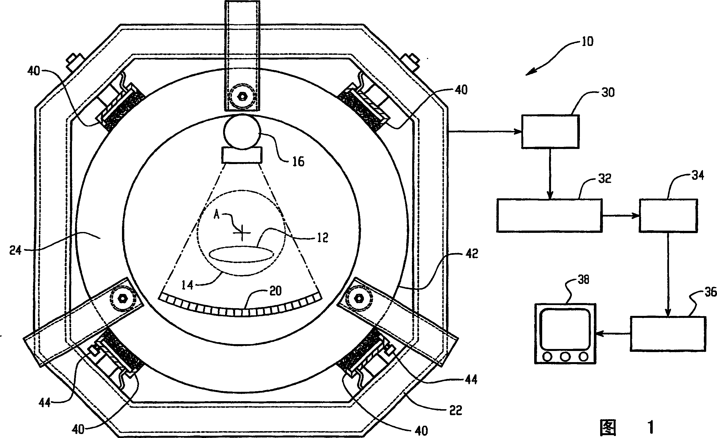
[0019] Referring to FIG. 1 , a CT scanner 10 includes a subject couch 12 for moving a subject thereon into or out of an imaging region 14 . X-rays from an X-ray source 16 are shaped and collimated into a fan-shaped beam, pass through the imaging region 14 and are detected by a detector component 20 distal to the imaging region 14 . In the third generation embodiment shown, the source 16 rotates simultaneously with the detector assembly 20 , and as the source 16 rotates about the axis A, the source 16 remains 180° from the detector assembly 20 around the imaging region 14 . Alternatively, a stationary ring of individual detectors on a stationary gantry 22 may replace the detector array 20, as in fourth generation CT scanners.

[0020] As the rotating gantry 24 rotates the X-ray source 16 around the object, the detected X-ray intensities are acquired into a data memory 30 . When collecting data, the reconstruction processor 32 performs convolution and back-projection algorithms...


PUM


Abstract

In a diagnostic imaging apparatus, a stationary gantry (24) and a rotating gantry (22) are interfaced by a plurality of air bearing elements (40). Lower air bearing elements bear the weight of the rotating gantry (22) which induce air hammering phenomena at a characteristic vibration frequency. To counteract the air hammering, a damping assembly (44) is mounted to at least one lower bearing element (40). The damping assembly (44) includes a damping mass (46) and an elastomeric connector (48) that are tuned to a frequency near the air hammer frequency to absorb the vibrational energy and damp the air hammer vibrations.

Description

technical field [0001] The present invention relates to medical imaging technology. In particular, the present invention relates to, and will be described in detail with reference to, a rotating gantry as included in third and fourth generation CT scanners. However, the present invention can also be applied in conjunction with other systems such as nuclear cameras using a rotating gantry, and the present invention is not limited to such applications as described above. Background technique [0002] Typically, third and fourth generation CT systems are equipped with ball or roller bearing systems. Due to the physical contact between the bearings and the rotating gantry, friction and wear occur during use of the scanner. In addition, the operating speed of the rotating gantry is limited by the bearings. [0003] In an effort to overcome these limitations of bearing systems for such medical imagers, hydraulic bearing systems are being used. Some hydraulic bearing systems in...

Claims


Application Information

Patent Timeline
Patent Type & Authority Applications(China)
IPC IPC(8): A61B6/03F16C32/06
CPCF16C32/067A61B6/035F16C32/0618F16C32/0666F16C2300/14F16C2316/10
Inventor W·C·布伦内特
Owner KONINK PHILIPS ELECTRONICS NV
Why Eureka
Try Eureka