
Mechanical rapping apparatus

A vibrator and mechanical technology, applied in the direction of electrostatic separation, electrode cleaning, etc., can solve problems such as poor vibration effect

Active Publication Date: 2005-10-26
WUHAN JEHOO HIGH TECH
View PDF6 Cites 20 Cited by
  • Summary
  • Abstract
  • Description
  • Claims
  • Application Information

AI Technical Summary

Problems solved by technology

The electromagnetic rapper does not need special maintenance and repair under normal working conditions. Compared with the traditional mechanical rapper, it overcomes many shortcomings and deficiencies, and its rapping effect has been improved, but over time, its rapping effect still not good

Method used


Image

  • Mechanical rapping apparatus
  • Mechanical rapping apparatus

Examples


Embodiment Construction

[0017] The present invention will be further described below in combination with specific embodiments.

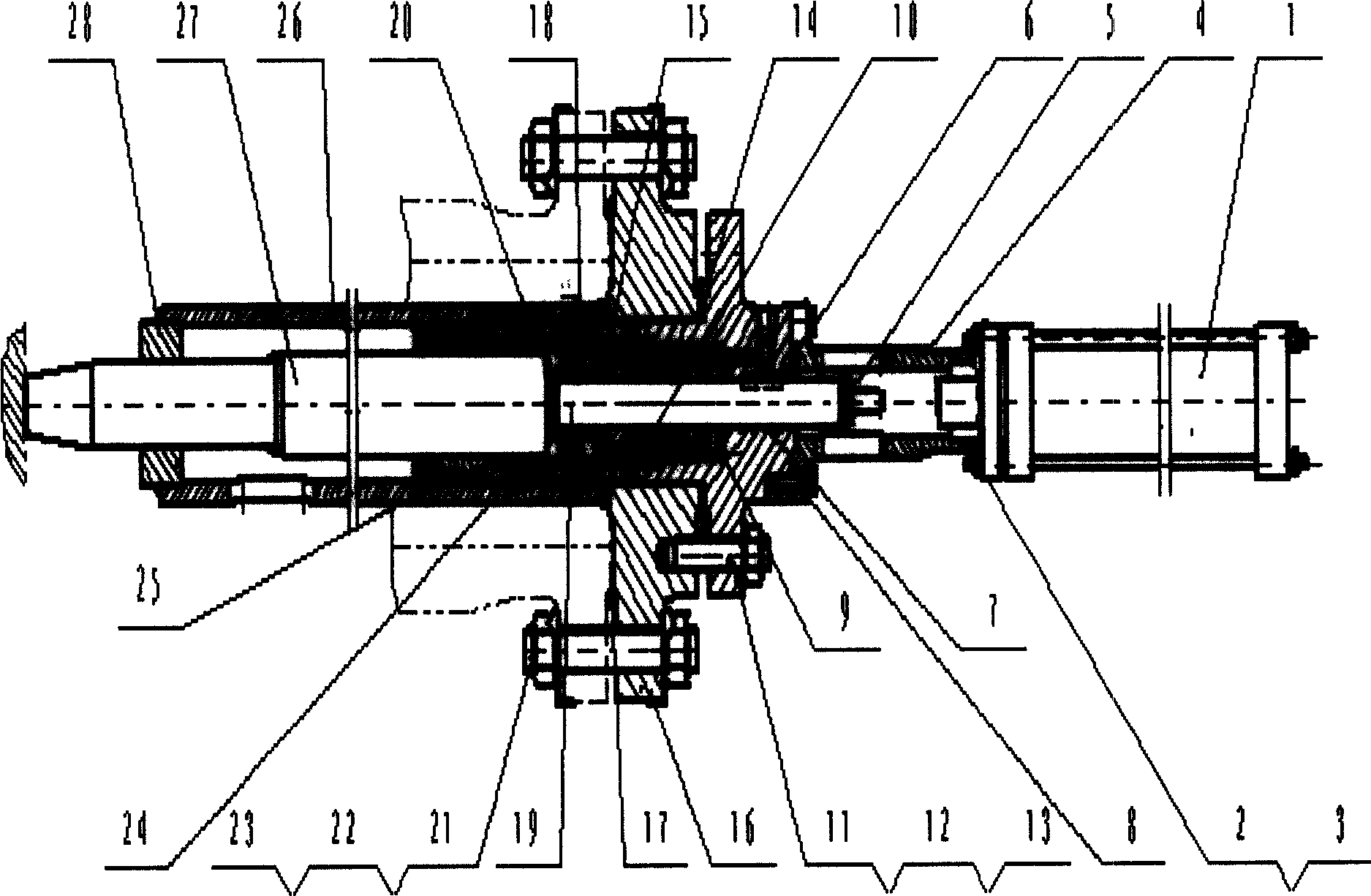
[0018] Place sealing gaskets between the piston guide cylinder 24 and the conduit 26 in the mechanical vibrator and connect them with bolts; check the piston rod 19 out of size and install the vibrator positioning bracket 4; the control cylinder 1 is connected with the positioning bracket 4. Put spring 9, piston 10, piston ring 15, sealing ring 18, piston rod 19, piston sleeve 20 and other parts into piston guide tube 24 and fix them; The position of the guide tube 26 is specified, and auxiliary measures are taken for positioning after measurement; the positioning bracket 4 is connected with the piston guide cylinder 24 through the bolt 8; ; The raised flange 16 is connected with the corresponding raised flange on the gasification equipment through a stud bolt 21 equipped with a nut 22 and a stop washer 23 . The static seal of the mechanical vibrator adopts the pressure ve...


PUM


Abstract

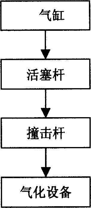
A mechanical shaker is composed of vibrating unit, sealing part, filtering and supporting-connecting unit. The piston rod is impacted by the kinetic energy generated from cylinder. The kinetic energy is then transferred to the impacting rod for impacting against the gasifying apparatus to remove the dust deposit and increase heat transfer efficiency.

Description

technical field [0001] The present invention relates to a mechanical rapper. When the rapper is working, the kinetic energy from the cylinder impacts the piston rod, and the piston rod transmits the kinetic energy to the striking rod, which strikes the gasification equipment. The vibrator belongs to the field of mechanical equipment. Background technique [0002] Compared with cyclone dust removal and bag dust removal [1] ,Electrostatic precipitator [2] Has its outstanding advantages. Therefore, electrostatic precipitators are widely used in metallurgy, cement, chemical industry, and light industry, and most of the rappers are developed based on electrostatic precipitators. The more common rappers used in various industries are mechanical rappers [3] and electromagnetic rappers [4] . The mechanical vibrator mainly includes hammer vibrator and spring cam vibrator. The device based on the cam produces periodic rapping action. The mechanical rapper has strong rapping f...

Claims


Application Information

Patent Timeline
Patent Type & Authority Applications(China)
IPC IPC(8): B03C3/76
Inventor 喻九阳常跃王成刚徐建民杨运辉胡中功
Owner WUHAN JEHOO HIGH TECH
Learn More