Resource utilization optimization method for transfer network

A resource optimization and transmission network technology, applied in the field of communication, can solve problems such as failure to achieve overall resource optimization and network topology changes, inability to realize reasonable utilization of existing network resources, and inapplicability of network performance evaluation to be built.

A resource optimization and transmission network technology, applied in the field of communication, can solve problems such as failure to achieve overall resource optimization and network topology changes, inability to realize reasonable utilization of existing network resources, and inapplicability of network performance evaluation to be built.

CN1688133AInactive Publication Date: 2005-10-26XIDIAN UNIV +1

Image

  • Resource utilization optimization method for transfer network
  • Resource utilization optimization method for transfer network
  • Resource utilization optimization method for transfer network

Examples


Embodiment Construction

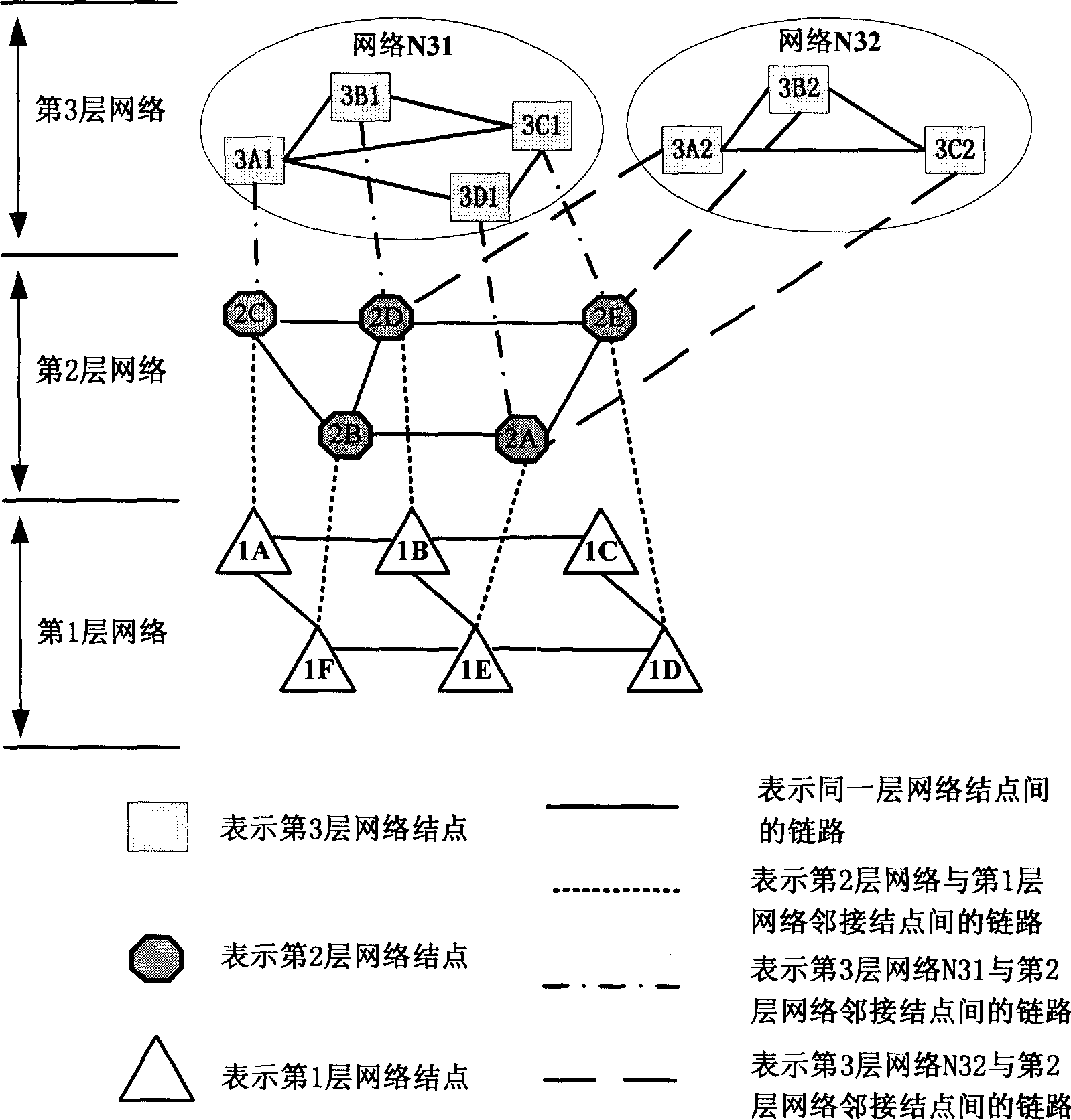
[0062] The present invention will be described in further detail below in conjunction with the accompanying drawings. For the convenience of description, the present invention takes M=3 as an example to describe the implementation method, but its principle is also applicable to the situation of M>3 or M=2. In order to facilitate the distinction between the link between adjacent nodes in the same layer and the two adjacent upper and lower layer node links, the present invention refers to the link between adjacent nodes in the same layer as the adjacent link between nodes, and refers to The links between two adjacent layer nodes are called inter-node adjacency links.

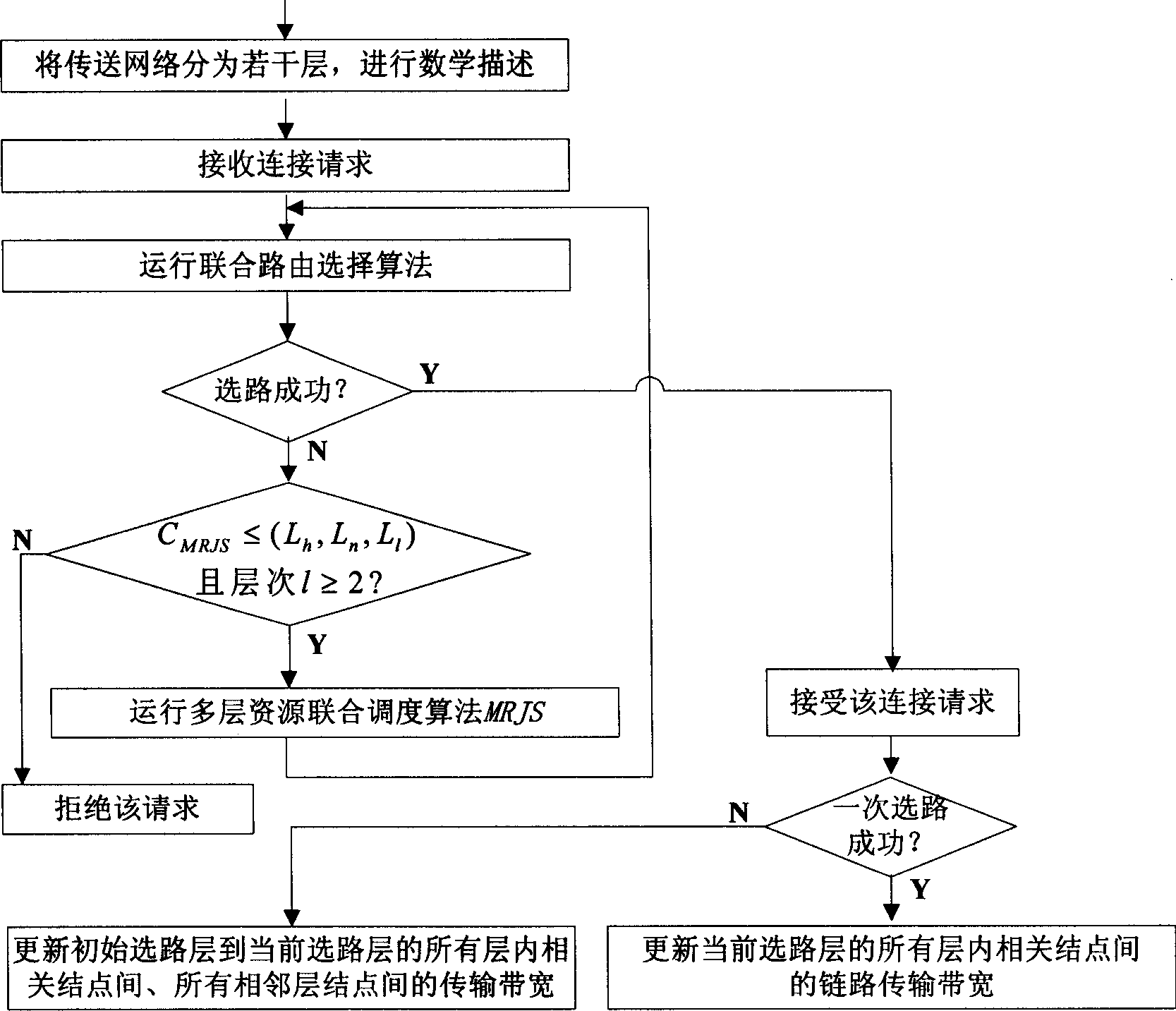
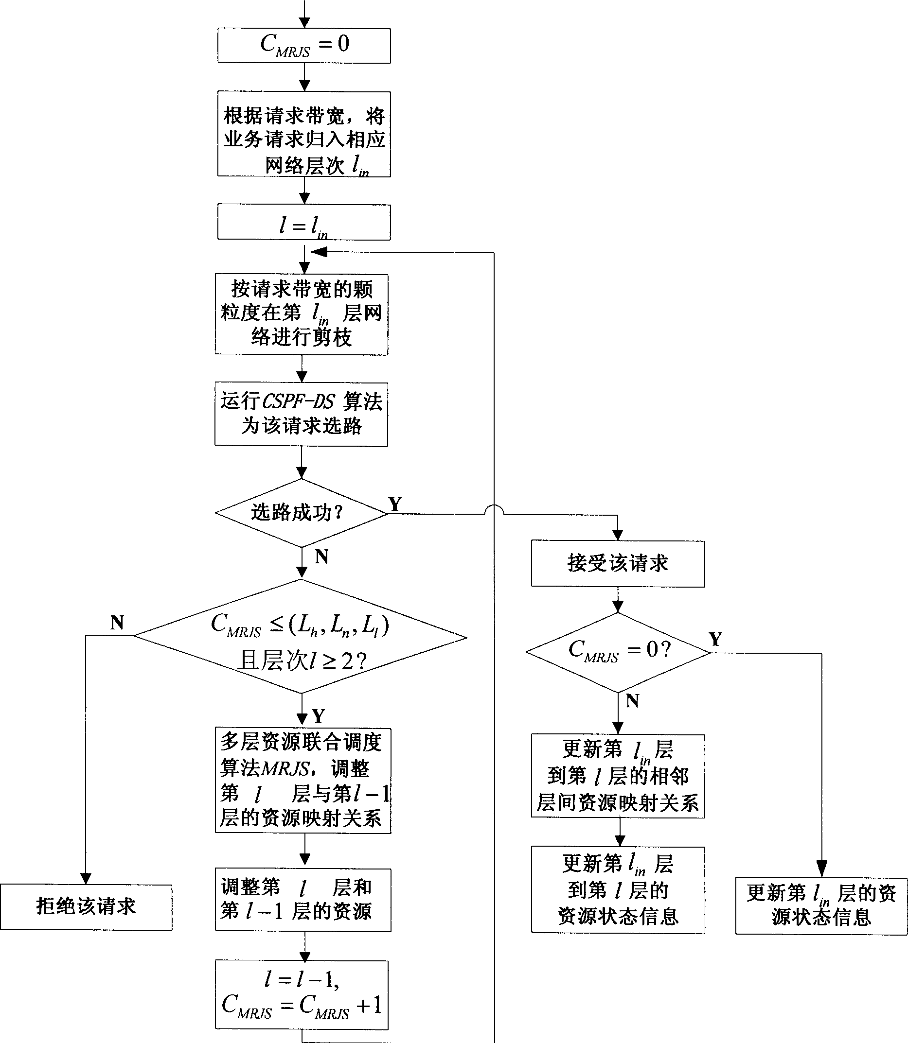
[0063] refer to figure 1 , the concrete implementation method of the present invention is as follows:

[0064] The first step is to divide the transport network into three layers according to the different actual network systems of the transport network, the network structure used by operators, or the fictitious...


PUM


Abstract

This invention discloses a method for laminating transmission nets, selecting joint routes and jointly optimizing multi-layer resource including the following steps: 1, expressing layering to the network, 2, jointly selecting routes according to the parameters of service request bandwidth and grade, link bandwidth usability, adjacent inter layer link transmission rate and hops, 3, calling the MRIS method based on the result of jointly selecting routes, 4, periodically calling the MRJS method to optimize the resource configuration, 5, carrying out the algorithm operation.

Description

technical field [0001] The invention belongs to the field of communication technology, and mainly relates to resource utilization technology in a communication network, in particular to a resource optimization method for a transmission network. technical background [0002] With the rapid development of telecommunication networks, computer networks and radio and television networks, the networks are showing a trend of mutual integration, and the network structure has undergone quantitative and even qualitative changes, and is evolving and transitioning to the next generation network NGN (Next Generation Network or NewGeneration Network). NGN is not a simple extension and superposition of the existing telecommunication network and IP network, but a transformation of the entire network framework and an overall solution. In order to protect existing network investment, the emergence and development of NGN is a gradual change rather than a sudden change. It is a network that rea...

Claims


Application Information

Patent Timeline
26 Oct 2005
Publication
CN1688133A
IPC
H04L12/24
Inventors
徐展琦; ηŽ‹ε»Ίεˆ©