A pressure regulation control method, device and system

A technology of voltage regulation control and control unit, which is applied in the field of electric power, can solve problems such as inability to coordinate with each other and unfavorable power system stability, and achieve the effect of avoiding repeated voltage adjustment and improving stability

Active Publication Date: 2018-03-16
STATE GRID ZHEJIANG YUYAO POWER SUPPLY +2
View PDF4 Cites 0 Cited by
  • Summary
  • Abstract
  • Description
  • Claims
  • Application Information

AI Technical Summary

Problems solved by technology

However, the voltage regulation function of the on-load tap changer and the voltage regulation function of the reactive power compensation device are implemented independently, and the two cannot be coordinated with each other. As a result, when the power supply voltage fluctuates, both of them will perform voltage regulation at the same time, which may cause regulation The final voltage is still greater than the upper limit or lower than the lower limit of the voltage, and the on-load tap changer and reactive power compensation device continue to regulate voltage, causing the on-load tap changer and reactive power compensation device to repeatedly adjust the supply voltage, which is not conducive to the power system. Stablize

Method used


Image

  • A pressure regulation control method, device and system
  • A pressure regulation control method, device and system
  • A pressure regulation control method, device and system

Examples


Embodiment 1

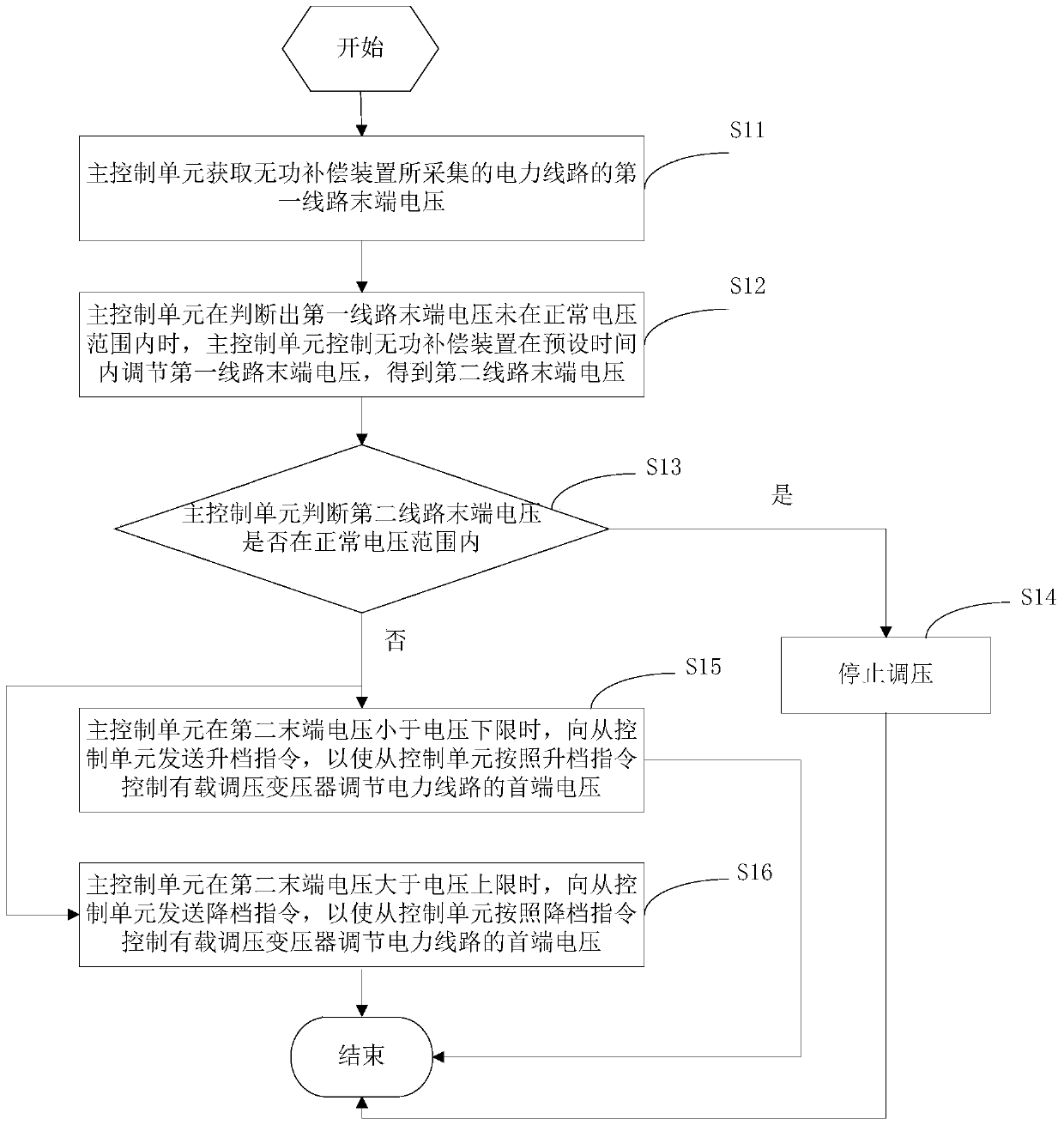
[0047] See figure 1 , which shows a flow chart of the pressure regulation control method provided by the present application, which may include the following steps:

[0048] Step S11: the main control unit acquires the first terminal voltage of the power line collected by the reactive power compensation device.

[0049] In this embodiment, the RS485 communication method is adopted between the main control unit and the reactive power compensation device. After the communication channel is established, the main control unit can obtain the terminal voltage of the power circuit collected by the reactive power compensation device.

[0050] Step S12: When the main control unit determines that the first terminal voltage is not within a normal voltage range, control the reactive power compensation device to adjust the first terminal voltage to obtain a second terminal voltage.

[0051] Step S13: The main control unit judges whether the second terminal voltage is within a normal volta...

Embodiment 2

[0068] and figure 1 Corresponding to the illustrated embodiment of the pressure regulation control method, the present application provides a pressure regulation control device, please refer to Figure 4 , which shows a schematic diagram of the logic structure of the voltage regulation control device provided by the present application. The voltage regulation control device includes: an acquisition unit 41, a first control unit 42, a judgment unit 43, a second control unit 44, and a first sending unit 45 and the second sending unit 46.

[0069] The obtaining unit 41 is configured to obtain the first terminal voltage of the power line collected by the reactive power compensation device.

[0070] The first control unit 42 is configured to control the reactive power compensation device to adjust the first terminal voltage to obtain a second terminal voltage when it is determined that the first terminal voltage is not within a normal voltage range.

[0071] The judging unit 43 i...

Embodiment 3

[0079] In this embodiment, a voltage regulation control system is shown, please refer to Figure 5 , The voltage regulation control system includes: a reactive power compensation device 51 , an on-load voltage regulation transformer 52 , a slave control unit 53 and a voltage regulation control device 54 .

[0080] Wherein, for the specific structure and functions of the pressure regulation control device 54, please refer to Embodiment 2, which will not be repeated here.

[0081] The voltage regulation control device 54 is connected with the reactive power compensation device 51 .

[0082] The slave control unit 53 is connected to the on-load voltage regulating transformer 52 .

[0083] The pressure regulating control device 54 is connected with the slave control unit 53 .

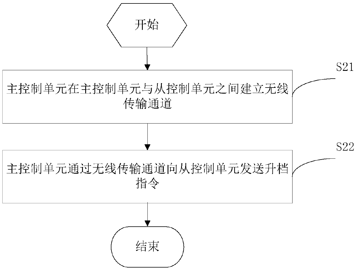
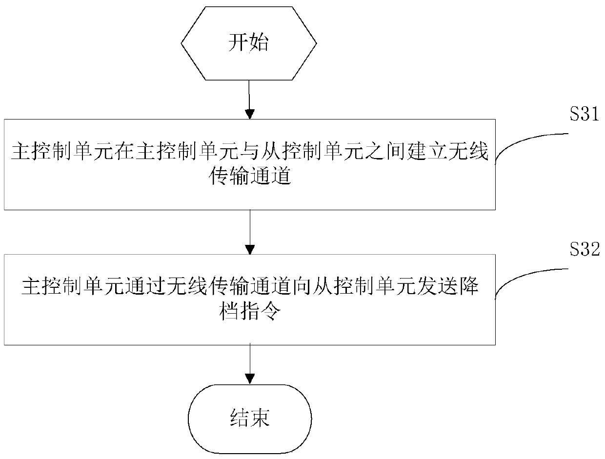
[0084] The slave control unit 53 is used to control the on-load voltage regulating transformer 52 to adjust the head-end voltage of the power line according to the upshift command sent by the voltage regu...


PUM


Abstract

The invention provides a voltage regulation control method, apparatus and system. The voltage regulation control method comprises the steps that a master control unit acquires a first terminal voltage of a power line collected by a reactive compensation apparatus; when the master control unit determines that the first terminal voltage is not within a normal voltage range, the master control unit controls the reactive compensation apparatus to regulate the first terminal voltage so as to obtain a second terminal voltage; the master control unit determines whether the second terminal voltage is in the normal voltage range; if yes, voltage regulation stops; if not, the master control unit sends a an upshift command to a slave control unit when the second terminal voltage is less than a voltage floor level; and the master control unit sends a downshift command to the slave control unit when the second terminal voltage is greater than a voltage ceiling level. According to the voltage regulation control method, apparatus and system, coordination of the reactive compensation apparatus and an on-load changing transformer is realized, repeated regulation of power circuit voltage is prevented, and power system stability is improved.

Description

technical field [0001] The present application relates to the field of electric power, in particular to a voltage regulation control method, device and system. Background technique [0002] Voltage is an important quality index in power system. During the normal operation of the power system, due to the fluctuation of the power supply voltage and the change of the load size, the power supply voltage of the system often changes, and the voltage change will cause abnormal operation of the electrical equipment, which directly affects production and daily life. [0003] Among them, the on-load voltage regulating transformer located at the head end of the power line and the reactive power compensation device located at the end of the power line both have the function of voltage regulation, and adjust the voltage when the power supply voltage changes. However, the voltage regulation function of the on-load tap changer and the voltage regulation function of the reactive power comp...

Claims


Application Information

Patent Timeline
Patent Type & Authority Patents(China)
IPC IPC(8): H02J3/12H02J3/16
CPCH02J3/12H02J3/16Y02E40/30
Inventor 陈高其王黎宁冯龙杰戴伟泽黄永钦
Owner STATE GRID ZHEJIANG YUYAO POWER SUPPLY
Why Eureka
Try Eureka