Control device

A control device and melt spinning technology, applied in general control system, program control, computer control, etc., can solve problems such as dependence

Active Publication Date: 2014-08-20
OERLIKON TEXTILE GMBH & CO KG
View PDF7 Cites 0 Cited by
  • Summary
  • Abstract
  • Description
  • Claims
  • Application Information

AI Technical Summary

Problems solved by technology

[0005] The disadvantage of this structure is that the structure of the control device is relatively fixedly dependent on the structure of the melt spinning machine

Method used


Image

  • Control device
  • Control device
  • Control device

Examples


Embodiment Construction

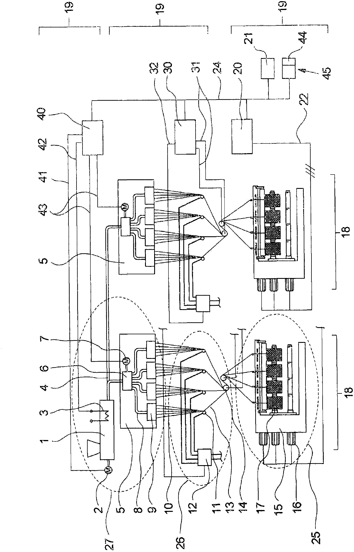
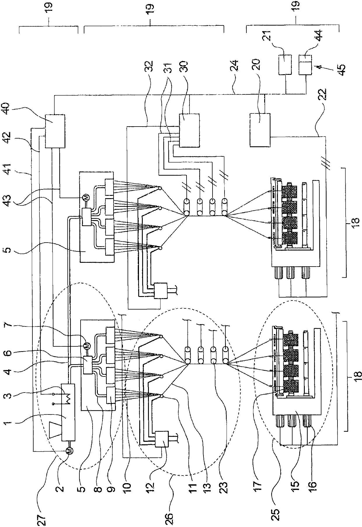
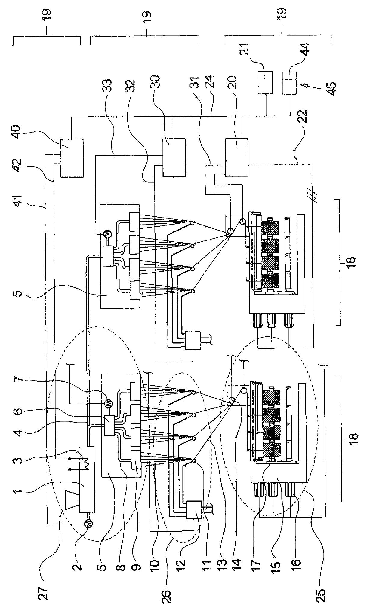
[0026] figure 1 A control device according to the invention for controlling a melt spinning machine is shown.

[0027] In order to produce a plurality of synthetic threads, a plurality of different working units are arranged successively in the material flow in the melt spinning machine in order to produce a plurality of synthetic threads from the polymer, for example in pellet form, in a plurality of working steps. In the illustrated embodiment of the melt spinning machine, the working mechanism chain starts with extruder 1 . The polymer material predetermined in the form of pellets is melted into a polymer melt by the extruder 1, which is driven by an extruder and distributed to several spin beams 5 via a plurality of melt lines The device 2 is driven and heated by means of the extruder heating device 3 . For the sake of clarity, only two spin beams 5 are described here. Usually more spin beams 5 are used. It is likewise also possible to use a plurality of extruders 1 or...


PUM


Abstract

The invention relates to a control device for controlling a melt-spinning machine comprising a plurality of work fields, which are each divided into a plurality of work stations. To achieve a modular adaptation to different embodiments of the melt-spinning machine, the control device is divided in a modular fashion into a plurality of control units, each of which is assigned to one individual work station. The coordination of the control units takes place via data exchange by means of data or control lines without a higher-level master controller.

Description

technical field [0001] The invention relates to a control device for controlling a melt spinning machine. Background technique [0002] When producing synthetic yarns with the aid of a melt spinning machine, the plastic melt coming out of a melt source, for example an extruder, is first distributed under pressure by means of a pump to a plurality of spinnerets with many spinning holes and spun into Multiple monofilament bundles. After cooling, the individual filament strands are each assembled into a thread and drawn off by means of a winding device and wound into a bobbin. Depending on the desired yarn quality, a further treatment is carried out before winding, for example by one or more godets of a drawing device. Here the threads are thermomechanically treated by varying peripheral speeds and temperatures as they pass through the godet sleeves. Furthermore, in addition to the aforementioned assemblies, auxiliary assemblies, for example tools for metered oiling, are pro...

Claims


Application Information

Patent Timeline
Patent Type & Authority Patents(China)
IPC IPC(8): D01D13/00B29C47/92B65H63/00G05B19/042B29C48/92
CPCB29C2947/92885B65H2701/31B29C2947/92209G05B2219/2229B29C2947/9258B29C2947/92019B65H63/00B65H54/70B29C2947/92409B29C47/92D01D13/00B29C2947/92952B29C47/367B29L2031/731B29C2947/92933B29C2947/92876B29C2947/926B29C47/0014B29C2947/92828B29C48/05B29C48/365B29C48/387B29C48/92B29C2948/92019B29C2948/92209B29C2948/92409B29C2948/9258B29C2948/926B29C2948/92828B29C2948/92876B29C2948/92885B29C2948/92933B29C2948/92952
Inventor A·绍尔
Owner OERLIKON TEXTILE GMBH & CO KG
Why Eureka
Try Eureka