
Parallel axes type automatic transmission

An automatic transmission, parallel shaft technology, applied in the direction of transmission, transmission parts, gear transmission, etc., can solve the problems of insufficient miniaturization and increased friction of automatic transmission, and achieve the effect of preventing air from entering and reducing load

Inactive Publication Date: 2005-11-02
HONDA MOTOR CO LTD
View PDF0 Cites 2 Cited by
  • Summary
  • Abstract
  • Description
  • Claims
  • Application Information

AI Technical Summary

Problems solved by technology

[0004] However, this parallel shaft type automatic transmission has a problem that the size reduction of the automatic transmission is not sufficient due to limited conditions such as the condition of the mating surface of the automatic transmission and the engine and the space when it is mounted on a vehicle.
In addition, splashes of lubricating oil from wet multi-disc clutches attached to each input shaft spread to the inner wall of the housing, causing aeration, or further increasing friction.

Method used


Image

  • Parallel axes type automatic transmission
  • Parallel axes type automatic transmission
  • Parallel axes type automatic transmission

Examples


Embodiment Construction

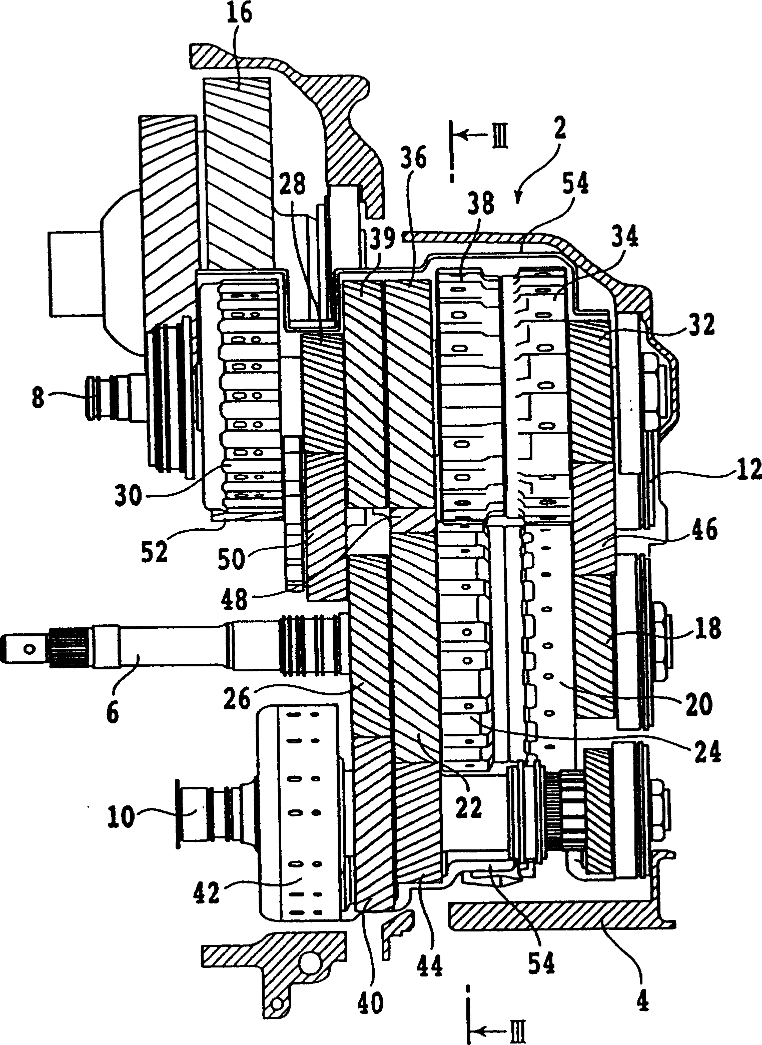
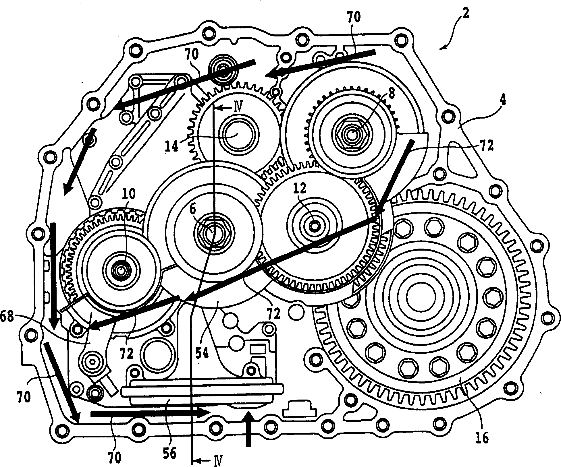
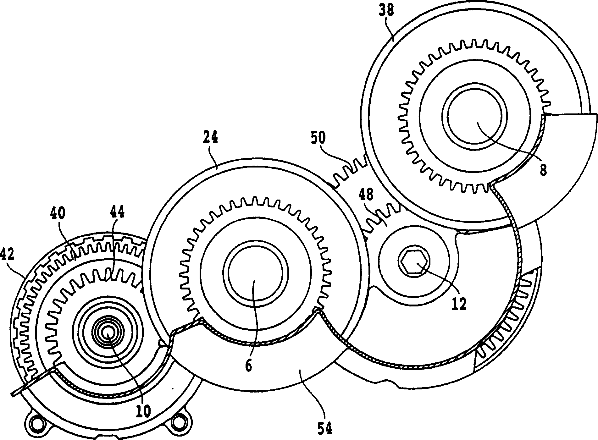
[0016] A parallel shaft automatic transmission according to an embodiment of the present invention will be described below with reference to the drawings. like figure 2 As clearly shown in the side view, the parallel shaft automatic transmission 2 has a first input shaft 6, a second input shaft 8, a third input shaft 10, an output shaft 12, and an idle shaft arranged parallel to each other in the transmission housing 4. Shaft 14.16 is the final reduction driven gear.

[0017] like Figure 4 As shown, the power of an engine (not shown) as a power source is input to the first input shaft 6 through a torque converter 62 connected to a crankshaft 60 of the engine. And, if figure 1 and Figure 4 As shown, a wet multi-disc clutch 20 for 3rd gear and a wet multi-disc clutch 24 for 6th gear as the highest gear are installed on the first input shaft 6, and a 3-disc clutch connected to the wet multi-disc clutch 20 is supported on the shaft. The first gear drive gear 18 and the six...


PUM


Abstract

The present invention provides a three-input-axis and one-output-axis parallel axis type automatic speed variator which can reduce the amount of the lubricant oil dispersing in the casing and can be miniaturized, and the automatic speed variator comprises a first input axis (6) which inputs the power from the power source, a second input axis which inputs the power through the first input axis (6) and a third input axis (10), and an output shaft. A plurality of wet-type multiple disc clutch for varying velocity are dispersedly arranged on the input axis, each input axis is axially supported with a driving gear connected with the wet-type multiple disc clutch arranged on each input axis, and a plurality of driven gears are fixed on the output axis. The number of the wet-type multiple disc clutches which are arranged on each input axis for speed varying is as follows: the number on the first input axis is above m, the number on the second input axis is above n, the number on the third input axis is less than m, wherein m is an integer above 2, and n is an integer above 3. The second input axis is arranged at the highest position, the first input is arranged at the middle position and the third input axis is arranged at the lowest position.

Description

technical field [0001] The present invention relates to a parallel shaft automatic transmission with three input shafts. Background technique [0002] Parallel shaft automatic transmission, between the input shaft and the output shaft arranged parallel to each other, a plurality of gear trains for speed change composed of the drive gear on the input shaft and the driven gear on the output shaft are arranged side by side, and each gear train One of the driving gear and the driven gear is supported on the corresponding shaft, and is connected with each gear row (for speed change) wet multi-disc clutch installed on the shaft, and is connected by selectively connecting each wet multi-disc clutch , so that the rotation of the input shaft is transmitted to the output shaft through the corresponding gear train, and the output is taken out through the final reduction drive gear fixed on the output shaft, with the same number of wet multi-disc clutches as the number of shifting stage...

Claims


Application Information

Patent Timeline
Patent Type & Authority Applications(China)
IPC IPC(8): F16H3/093F16H57/021F16H57/023F16H57/04
CPCF16H57/0494F16H57/0423F16H57/043Y10T74/19991Y10T74/2186Y10T74/19233
Inventor 木村光男武田元雄津幡义道
Owner HONDA MOTOR CO LTD
Learn More