Spray type dust separator

A dust collector and spray type technology, applied in the field of machinery, can solve the problems of damage to the motor, high equipment prices, and the inability to recycle metal powder, and achieve the effects of increasing the contact area, wide application range and high adsorption rate.

Inactive Publication Date: 2005-11-09
玉环太平洋机械有限公司
View PDF1 Cites 26 Cited by
  • Summary
  • Abstract
  • Description
  • Claims
  • Application Information

AI Technical Summary

Problems solved by technology

However, the structure of the dust collector is relatively complicated and the equipment price is high; at the same time, the wet dust will stick to the inside of the ventilator, which may damage the motor; in addition, the metal powder contained in the dust cannot be recycled

Method used


Image

  • Spray type dust separator
  • Spray type dust separator
  • Spray type dust separator

Examples


Embodiment Construction

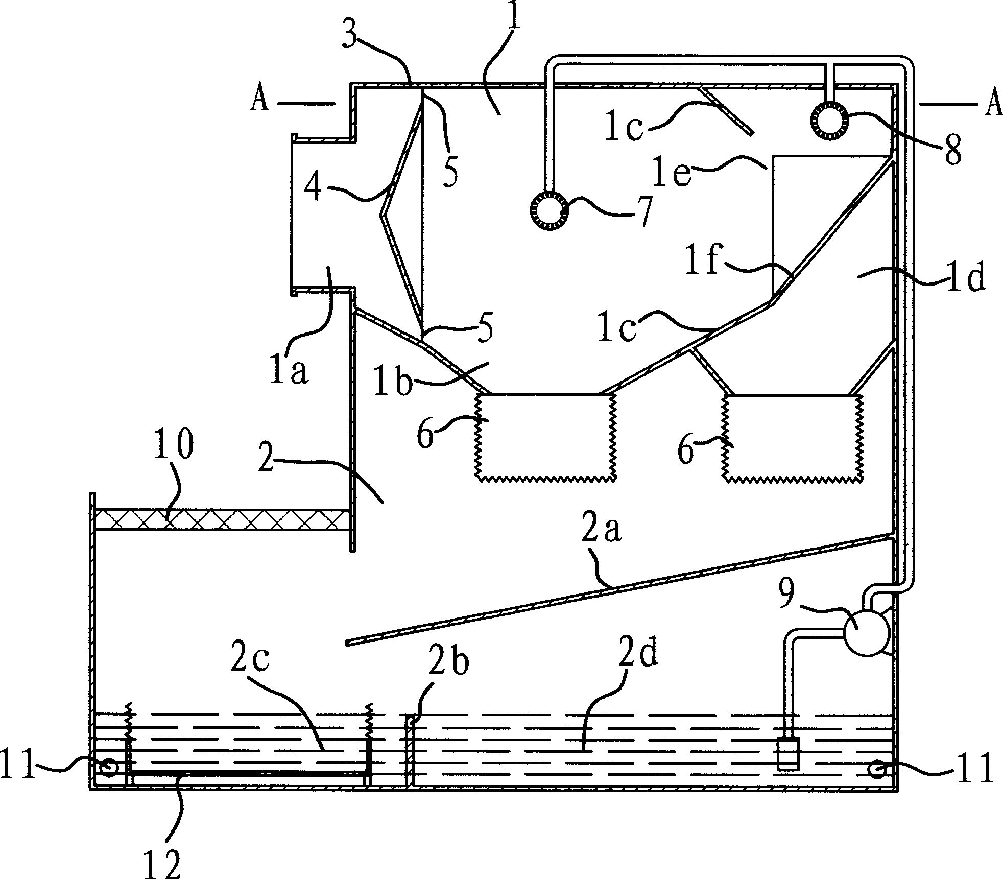
[0020] Such as figure 1 As shown, the spray dust collector transports the dust airflow into the dust collector through the air pipe, and then performs dust removal. It includes a hollow casing 3, and the partition divides the casing 3 into two chambers: a spray chamber 1 and an airflow chamber 2. The spray chamber 1 is provided with a spray head 7, through which the spray head 7 sprays water mist to spray the air flow in the chamber, so that the water mist absorbs the dust in the air flow, and when the water flow passes through the filter box 6, the dust is retained At the bottom of filter box 6.

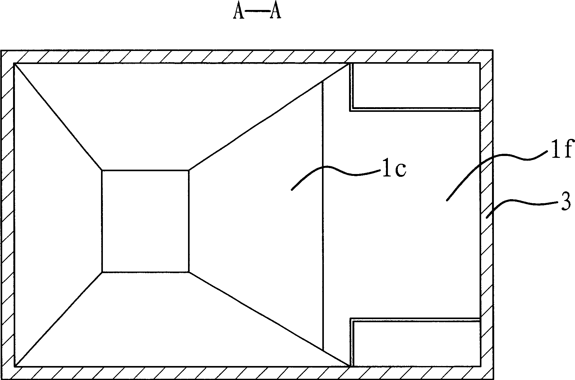
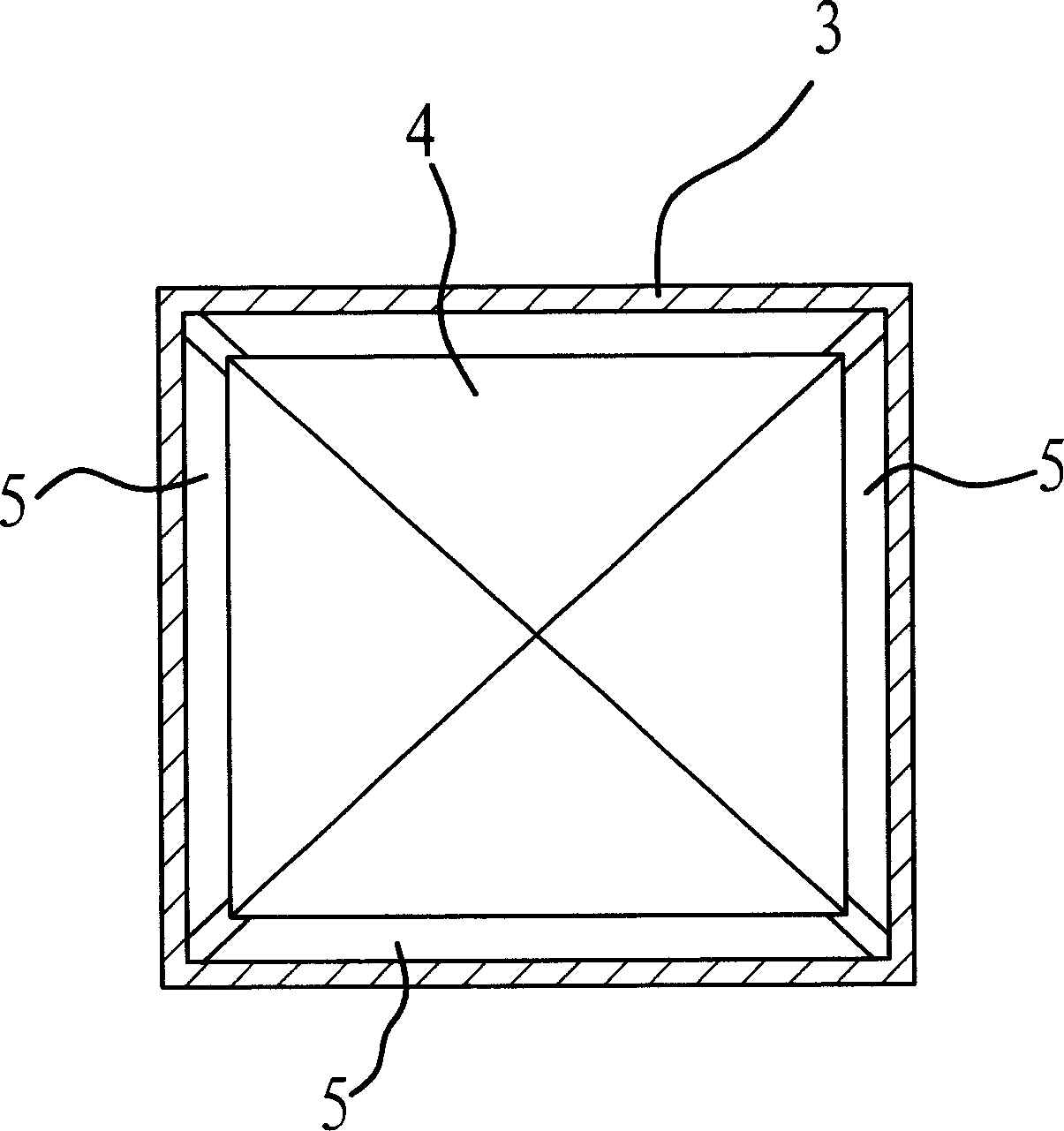
[0021] Such as figure 1 and image 3 As shown, there is an air inlet 1a on the casing 3 . A conical air-dispersing partition 4 is fixedly attached to the casing 3, which is close to the air inlet 1a. In this embodiment, the air-dissipating partition 4 is pyramid-shaped. An air inlet gap 5 is left between the surroundings of the diffused air partition 4 and the housing 3 , and ...


PUM


Abstract

A shower-type duster is composed of composed of a casing with air inlet, a partition for dividing the cavity in the casing into showering cavity and airflow cavity, a wind-gathering bulkhead for dividing the showering cavity into front and back showering cavities, two filters arranged in two channels between airflow cavity and front and back showering cavities, and two showering nozzles for both showering cavities.

Description

technical field [0001] The invention belongs to the technical field of machinery and relates to a dust removal device, in particular to a dust remover which adopts a spraying method to remove dust. Background technique [0002] In the industrial production process, a large amount of dust or solid particles are often generated. These dust or solid particles are generally drawn out by a fan. However, if it is discharged directly into the air, it will pollute the environment and does not meet environmental protection requirements. Therefore, it needs to be filtered through a dust collector. [0003] There are many types of existing dust catchers with different structures, some of which have also applied for patents. At present, the ideal way is to remove dust by water spraying. Such as Chinese patent 01220578.3 provides a kind of " water spray ventilation deduster ", and it is made up of ventilator, dustproof housing, water baffle and cyclone device, and cyclone device comp...

Claims


Application Information

Patent Timeline
Patent Type & Authority Applications(China)
IPC IPC(8): B01D47/06
Inventor 陈美青
Owner 玉环太平洋机械有限公司
Why Eureka
Try Eureka