High precision measuring method for stretching displacement

A displacement measurement, high-precision technology, applied in the field of high-sensitivity measurement of tensile displacement, can solve the problems of non-ideal method of tensile displacement of flexible materials, inability to give accurate values ​​of materials, low displacement measurement accuracy, etc. Easy to master, high measurement accuracy

Inactive Publication Date: 2005-11-09
SUZHOU UNIV
View PDF0 Cites 32 Cited by
  • Summary
  • Abstract
  • Description
  • Claims
  • Application Information

AI Technical Summary

Problems solved by technology

On the existing extensometer, the following problems exist in the measurement of tension and compression displacement by the displacement sensor: 1. The elongation measured by the displacement sensor is the displacement of the gripper at the end of the displacement sensor installed during tension and compression, rather than the elongation of the working section. The end is a non-uniform strain area, and the middle working area is a uniform strain area, so a large error will be introduced
2. The test piece may slip during the stretching process, and in this case, the existing displacement sensor also includes this displacement into the deformation and elongation of the test piece, which brings a large error to the calculation of the elongation
3. The displacement measurement accuracy of the existing displacement sensor is not high, and the accurate value of the strain during the stretching process of the material cannot be given
At present, there is no ideal method for measuring the tensile displacement of flexible materials

Method used


Image

  • High precision measuring method for stretching displacement

Examples


Embodiment 1

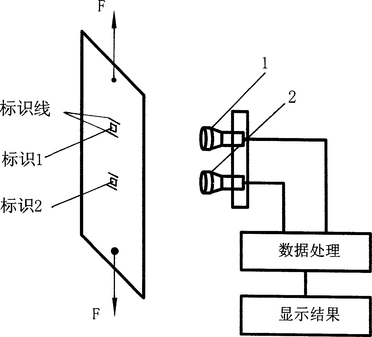
[0017] Referring to accompanying drawing 1, mark 1, mark 2 are respectively set on the working section of the tested piece, and its distance is taken as 100mm, and the digital image imaging device 1 corresponding to collecting mark 1 signal and the digital image imaging device corresponding to collecting mark 2 signal Device 2 uses the same CCD with a lens focal length of 35mm. The imaging target surfaces of the two CCDs are located in the same plane. The two CCDs respectively collect a digital image corresponding to a logo, and the two digital images are respectively stored in frames 1 and 2 of the image card memory.

[0018] The test piece is loaded by the tensile testing machine, and then the digital images of the two marks after the deformation of the test piece are respectively collected and stored in frames 3 and 4, and the computer is used to perform correlation search operations on 1, 3 and 2 and 4 respectively, and calculate The number of pixels that the two marks mov...

Embodiment 2

[0020] Paste two logos on the metal copper rod at a distance of 100mm, use CCD1 and CCD2 as digital image imaging devices, the focal length of the CCD lens is 35mm, the two CCD imaging target surfaces are located in the same plane, the CCD is located in front of the logo and the CCD target surfaces are connected Parallel to the connecting line of the two logos. Collect two digital images and store them in two frames of image card memory 1 and 2 respectively, and record the current ambient temperature. Use water vapor to raise the temperature of the copper rod to 100°C, and then collect the digital images of the two marks after the deformation of the test piece, store them in frames 3 and 4, use the computer to perform correlation search operations on 1, 3 and 2, 4 respectively, and calculate them respectively The number of pixels that the two marks move on the CCD target surface, the displacement of the two marks is calculated by the magnification of the two CCD imaging system...


PUM


Abstract

The invention discloses a kind of high accuracy method to measure pull and stretch displacement. It adopts two digital vidicons to shoot, establish two markings in the work segment of the test piece, and make these two digital vidicons' imaging targets form in one plane. The vidicons locate in front of the markings and their imaging targets' on-line runs parallel with two markings' on-line. The vidicons respectively collect the two light signals which are in response to the changed markings after movement. At last, by inputting these signals which are converted into numerical picture signals into a computer to process, output the measure result. Because the invention adopts two vidicons to observe two markings staying on the work segment respectively, it can remove the measure error margin produced by the test piece's displacement when the piece is in the pull and stretch process; The method also has the advantage of high accuracy, no contact and precise real time, so it can be applied vastly in future.

Description

technical field [0001] The invention relates to a method for measuring the length variation and strain of a test piece under heat or stress, in particular to a non-contact, high-sensitivity method for measuring tensile displacement using optical technology. Background technique [0002] The strength and deformation characteristics of materials under the action of external force are called the mechanical properties of materials. Tensile test is the main test to determine the mechanical properties of materials. When doing the tensile test, the material is made into a standard sample so that its geometric shape and stress conditions can meet the requirements of axial tension. When the specimen is stretched, the tensile displacement of the specimen is measured by the displacement sensor installed at the moving end of the testing machine. The strain is calculated by the ratio of the tensile displacement value measured by the displacement sensor to the o...

Claims


Application Information

Patent Timeline
Patent Type & Authority Applications(China)
IPC IPC(8): G01N3/28
Inventor 王琰蕾李明姜锦虎杨勇
Owner SUZHOU UNIV
Why Eureka
Try Eureka