
Controllable inductance of AC field magnetic amplifier and its application

A technology of magnetic amplifier and AC excitation, applied in variable inductors, inductors, AC power input conversion to AC power output, etc., can solve the problem of cumbersome process, complex control circuit, and adjustable DC voltage E circuit cannot work normally and other problems, to achieve the effect of simple process, wide range of application and simple circuit

Inactive Publication Date: 2005-11-09
中山市高上普照节能设备有限公司
View PDF0 Cites 6 Cited by
  • Summary
  • Abstract
  • Description
  • Claims
  • Application Information

AI Technical Summary

Problems solved by technology

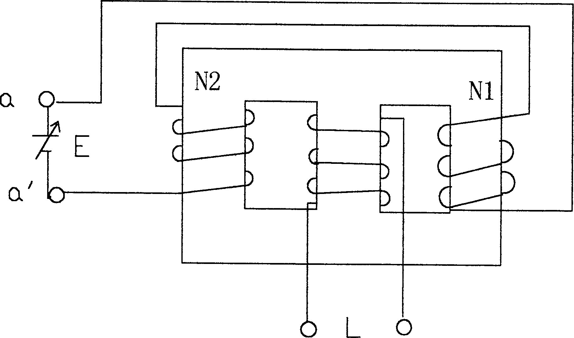
Although this method can use the magnetic amplifier to adjust the working voltage value of the load, this method has the following defects: ① The process of making the output terminals a and a' of the control winding have no AC voltage output is particularly cumbersome, if the output terminal a of the control winding 、If there is voltage in a', it will affect the adjustable DC voltage E circuit connected to the output terminals a and a', so that the adjustable DC voltage E circuit cannot work normally. ②A special adjustable DC voltage E circuit is required , making the entire control circuit complex

Method used


Image

  • Controllable inductance of AC field magnetic amplifier and its application
  • Controllable inductance of AC field magnetic amplifier and its application
  • Controllable inductance of AC field magnetic amplifier and its application

Examples


Embodiment Construction

[0017] The present invention will be further described below in conjunction with the accompanying drawings and embodiments.

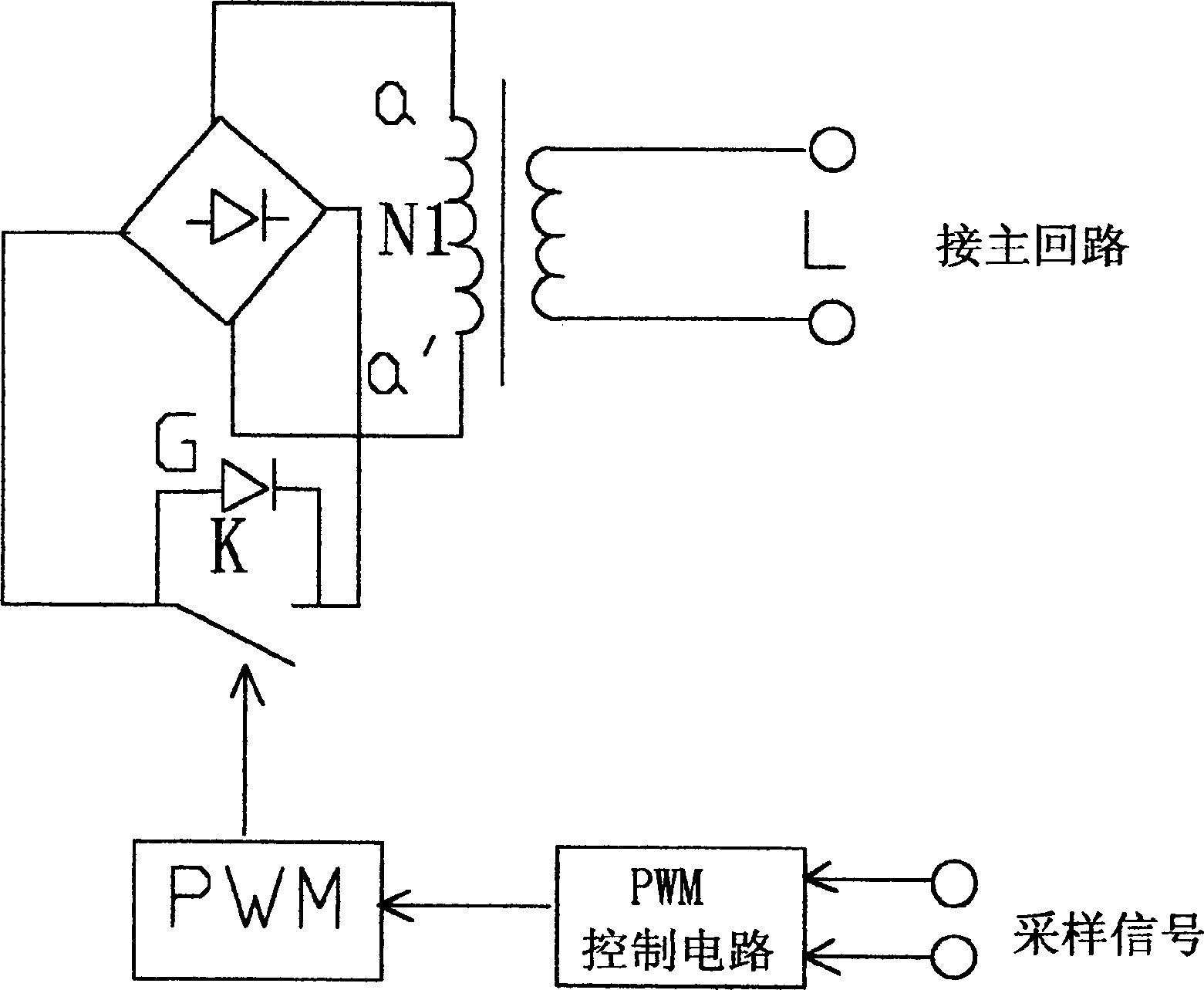
[0018] In the present invention, two windings are individually wound on one iron core column, one group is the main winding L, and the other group is the control winding N1, and a bridge rectifier circuit is connected to both ends of the control winding N1, and the output of the rectifier circuit A switch K controlled by the pulse width modulator PWM is connected in parallel at the terminal, a freewheeling diode G is also connected in parallel at both ends of the switch K, the PWM control terminal of the pulse width modulator is also connected with an output terminal of a PWM control circuit, and the PWM control circuit The input terminal connects both ends of the load.

[0019] The working principle of the present invention is: when the main winding L has an alternating current, an alternating electromotive force (voltage) is generated at both ends of ...


PUM


Abstract

This invention relates to a controllable inductor of an AC excitation amplifier and its usage characterizing in winding two windings on one iron-core post separately, one winding is a master one, the other is a control one, a commutating circuit is cut-in to both ends of the control winding, the output of the commutating circuit is parallel to a switch controlled by PWM. Said controlled inductor is especially suitable for high strength gas discharge lamp light adjusting energy saving circuit.

Description

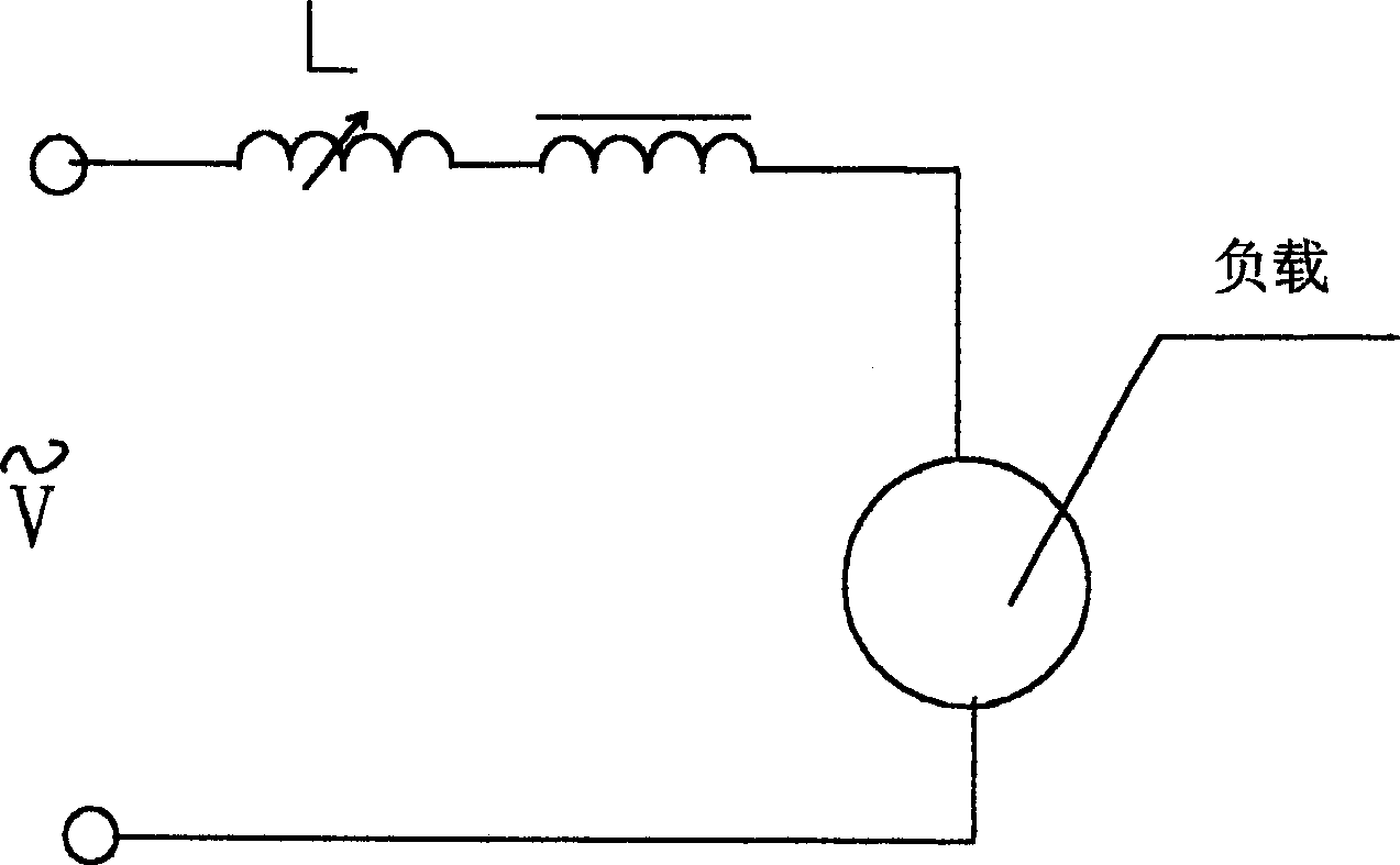
technical field [0001] The invention belongs to a working voltage and current control circuit for inductive loads, in particular to a controllable inductance of an AC excitation amplifier and its application. Background technique [0002] At present, in controlling inductive loads, especially in circuits using magnetic amplifiers to adjust and control AC power, the method often used is to connect a main winding L of a magnetic amplifier in series in the main circuit of the load (see figure 1 ), the magnetic amplifier is to wind the AC windings N1 and N2 on the two side columns of the Japanese-shaped iron core respectively (see figure 2 ), wherein the control windings N1 and N2 are reversely connected in series, and when an AC current is generated on the main winding L of the magnetic amplifier, the output terminals a and a' of the control winding have no AC voltage output, and then the output terminals a and a' Both ends of the adjustable DC voltage E a...

Claims


Application Information

Patent Timeline
Patent Type & Authority Applications(China)
IPC IPC(8): H02P13/12
Inventor 刘双喜
Owner 中山市高上普照节能设备有限公司
Learn More