Coil component of electromagnetic relay

A technology for electromagnetic relays and coil components, which is applied to electromagnetic relays, detailed information of electromagnetic relays, relays, etc., can solve the problems of complicated coil winding process, reduced coil winding space, and difficulty in miniaturizing relays, so as to eliminate virtual welding. The effect of avoiding hidden dangers, improving winding space, and improving work reliability

Active Publication Date: 2005-11-16
XIAMEN HONGFA SIGNAL ELECTRONICS CO LTD
View PDF3 Cites 4 Cited by
  • Summary
  • Abstract
  • Description
  • Claims
  • Application Information

AI Technical Summary

Problems solved by technology

CN99101704 invention patent discloses an electromagnetic relay. After the coil is wound and before the base is integrally injected, the lead piece of the coil and the coil lead-out pin of the relay must be welded together. The hidden danger of welding, and additional processing equipment is required, and the processing process is long and complicated
The invention patent application with the application number CN03141569 discloses an ultra-small high-sensitivity communication relay. Since the magnetic steel seat hole is set in the middle of the coil frame, the winding space of the coil is significantly reduced, which will lead to a significant increase in the efficiency of the magnetic circuit. The reduction makes it difficult to further miniaturize the relay, and the winding process of its coil is complicated, that is, it needs to cross the magnetic steel seat hole in the middle of the coil frame during the winding process, which increases the production cost

Method used


Image

  • Coil component of electromagnetic relay
  • Coil component of electromagnetic relay
  • Coil component of electromagnetic relay

Examples


Embodiment 1

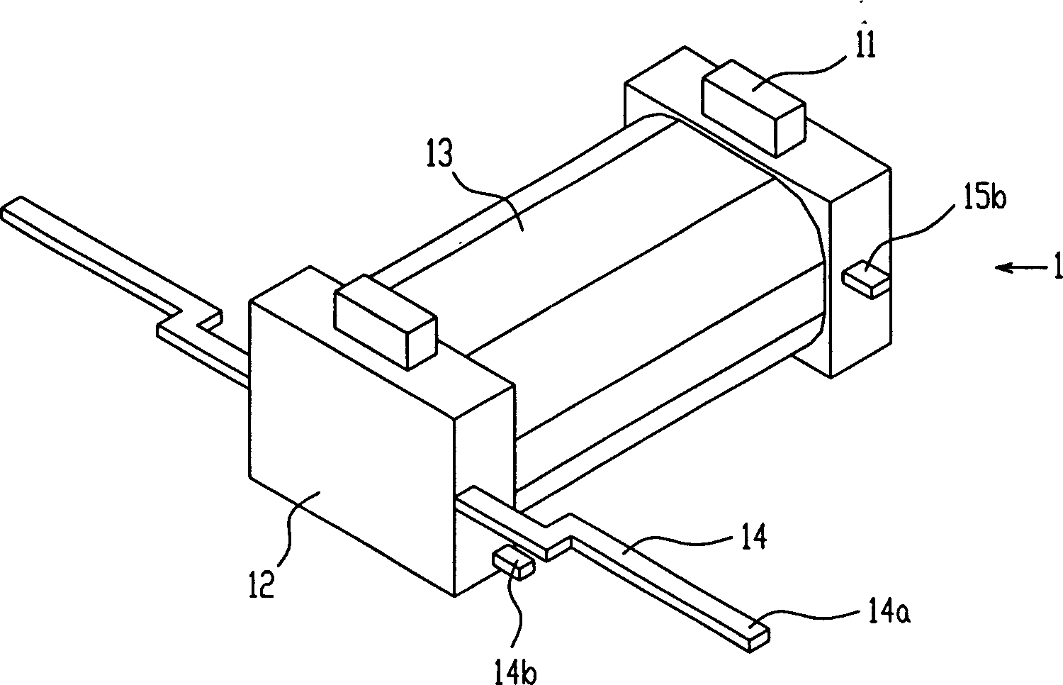
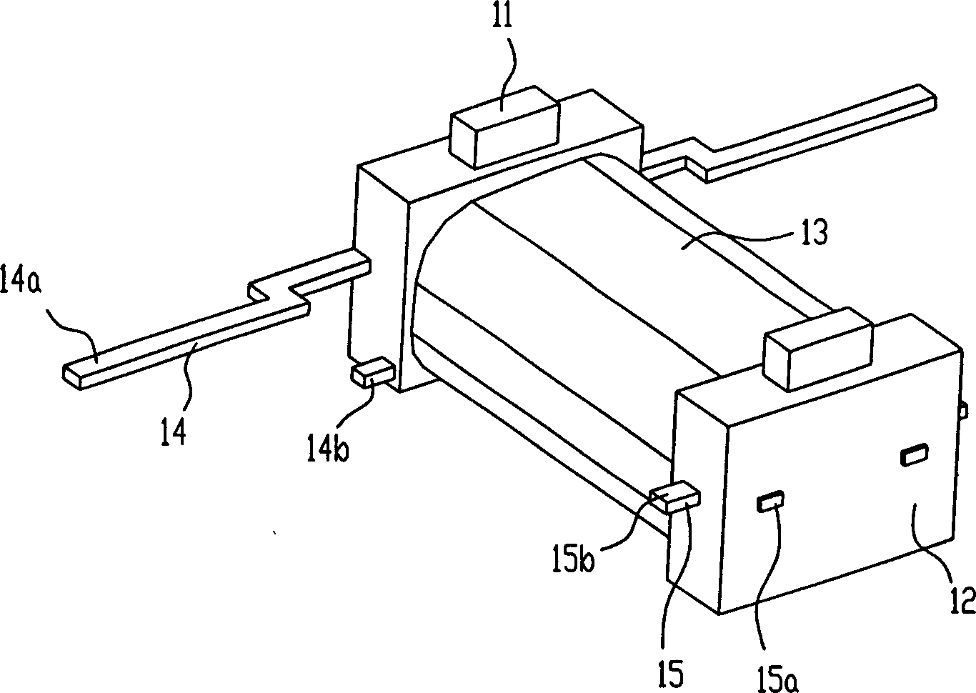
[0025] like Figure 1-3 As shown, the present invention is provided with the C-shaped part 11 that is made of magnetic steel and magnetizer, and coil 13 is wound on the insulating bobbin 12, and lead pin 14,15 and insulating bobbin 12 are injection molded together, and lead pin 14,15 have Two free ends, one free end 14a, 15a is the coil lead-out pin of the relay, and the other free end 14b, 15b is the wrapping end of the coil. When the coil 13 is a single coil, the lead pin 15 only plays the roles of support and positioning in the processing process; when the coil 13 is a double coil, its function is the same as that of the lead pin 14.

[0026] The lead-out mode of the coil 13 is that the two lead-out ends of the coil 13 are respectively wound on the lead-out ends 14b and 15b, or respectively wound on the lead-out ends 14b or 15b, and then they are welded together.

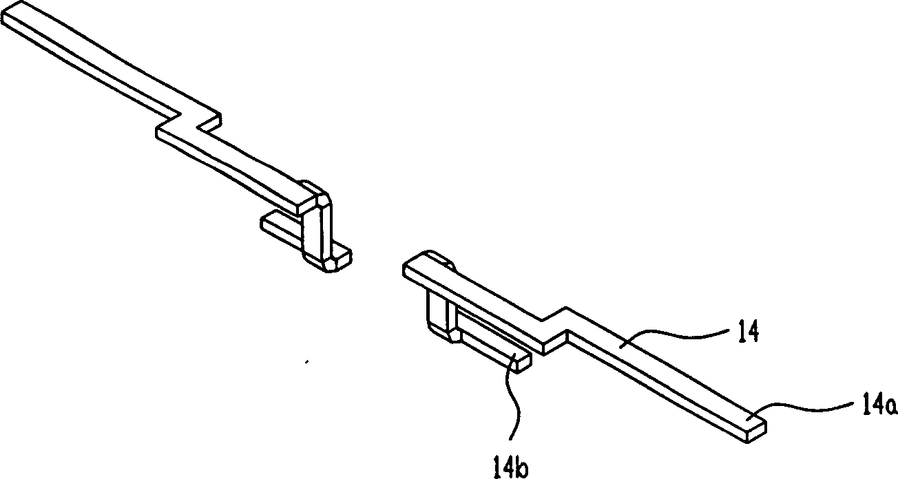
[0027] The lead pin 14 of the present invention includes two free ends, one free end 14a is the coil lead-out...

Embodiment 2

[0030] Figure 5 Given another embodiment of the present invention, the insulating bobbin 12 is not integral, but at least includes two parts 12a, 12b, which respectively wrap the parts below the pole faces 11a, 11b of the C-shaped component composed of the magnetic steel and the magnetizer, That is to say, the C-shaped part made of magnetic steel and magnetizer has two pole faces 11a, 11b and the middle part is not wrapped by insulating material, but another insulating material is used in the middle part of the C-shaped part 11 composed of magnetic steel and magnetizer. 16 wraps it up, also can be coated with an insulating layer on the surface of the C-shaped part 11 that magnetic steel and magnetizer constitute. exist Figure 5 Other tags in the figure 2 same.

Embodiment 3

[0032] Image 6 Provided another embodiment of the present invention, the two ends of the insulating bobbin 12 or the center of the coil are left with a magnetic conductor 11c or a magnetic steel 11d seat hole, and the magnetic conductor 11c or the magnetic steel 11d is placed in the subsequent process into the seat hole. It is also possible to replace the C-shaped component 11 formed by the magnetic steel 11d and the magnetic conductor 11c with a C-shaped magnetic conductor 11 composed of several parts. The C-shaped magnetic conductor 11 is divided into several parts similar to the above-mentioned magnetic steel 11d and the magnetic conductor 11c. .

[0033] like Figure 7 As shown, an embodiment of the application of the relay of the present invention is given, see Figure 2-6 , The electromagnetic relay includes a housing 4, an armature part 3, and a contact base part 2 that injects the coil part 1 and the static spring together. The coil part 1 includes a C-shaped part...


PUM


Abstract

The invention discloses coil assembly with C-shaped magnetic guiding part of electromagnetic relay. The coil assembly includes C-shaped magnetic guiding part, insulating coil former, coil, and at least one pair of pin of lead out wire. Coil is wound on the insulating coil former. Each pin of lead out wire includes two free ends; one free end is pin of lead out wire of relay, and the other free end is a wrapping end for coil. In the invention, the said wrapping end and the pin of lead out wire of relay are combined as an integrated pin of lead out wire, which is injection-molded with part of coil former. Thus, the invention possesses advantages of omitting procedure for welding contact piece and lead out piece etc, eliminating cold joint, simplifying production technique, miniaturized relay, and raising stability, acceptability of products as well as production efficiency etc.

Description

technical field [0001] The invention relates to an electromagnetic relay, in particular to an electromagnetic relay coil part with a C-shaped conductive magnet, or a C-shaped conductive magnet and magnetic steel. Background technique [0002] Electromagnetic relays are widely used in automatic control equipment. Due to the needs of technological development, relays are required to be more compact in structure, smaller in size, higher in sensitivity, longer in service life and higher in reliability. Utility model patent No. CN02217796 discloses an ultra-small high-sensitivity relay. After the coil is wound and loaded into the base, the lead piece of the coil and the coil lead-out pin of the relay need to be welded together. CN99101704 invention patent discloses an electromagnetic relay. After the coil is wound and before the base is integrally injected, the lead piece of the coil and the coil lead-out pin of the relay must be welded together. There are hidden dangers of weld...

Claims


Application Information

Patent Timeline
Patent Type & Authority Applications(China)
IPC IPC(8): H01H50/44
CPCH01H50/36H01H50/443
Inventor 王俊青
Owner XIAMEN HONGFA SIGNAL ELECTRONICS CO LTD
Why Eureka
Try Eureka