Pile tip displacement regulating device

A technology of displacement adjustment and pile tip, which is applied in the direction of construction and infrastructure engineering, etc., can solve the problems of low bearing capacity, huge consumption of manpower and material resources, troubles, etc., and achieve the effect of convenient adjustment and simple structure

Active Publication Date: 2005-11-23
View PDF0 Cites 19 Cited by
  • Summary
  • Abstract
  • Description
  • Claims
  • Application Information

AI Technical Summary

Problems solved by technology

However, the composite pile foundation has certain limitations: in order for the foundation soil to participate in bearing the upper load, the pile foundation must have a large settlement, so the composite pile foundation can only use friction piles or end-bearing friction piles with a small end-bearing effect ; Since friction piles or end-bearing friction piles generally have low bearing capacity, composite pile foundations can only be used in multi-storey or small high-rise buildings.
The existence of these old piles increases the difficulty of the construction of new pile foundations in this area, which is not only cumbersome to handle, but also consumes huge manpower and material resources
In addition, if it is not handled well, it is easy to cause hidden dangers of water leakage in the basement of the building.

Method used


Image

  • Pile tip displacement regulating device
  • Pile tip displacement regulating device
  • Pile tip displacement regulating device

Examples


Embodiment 1

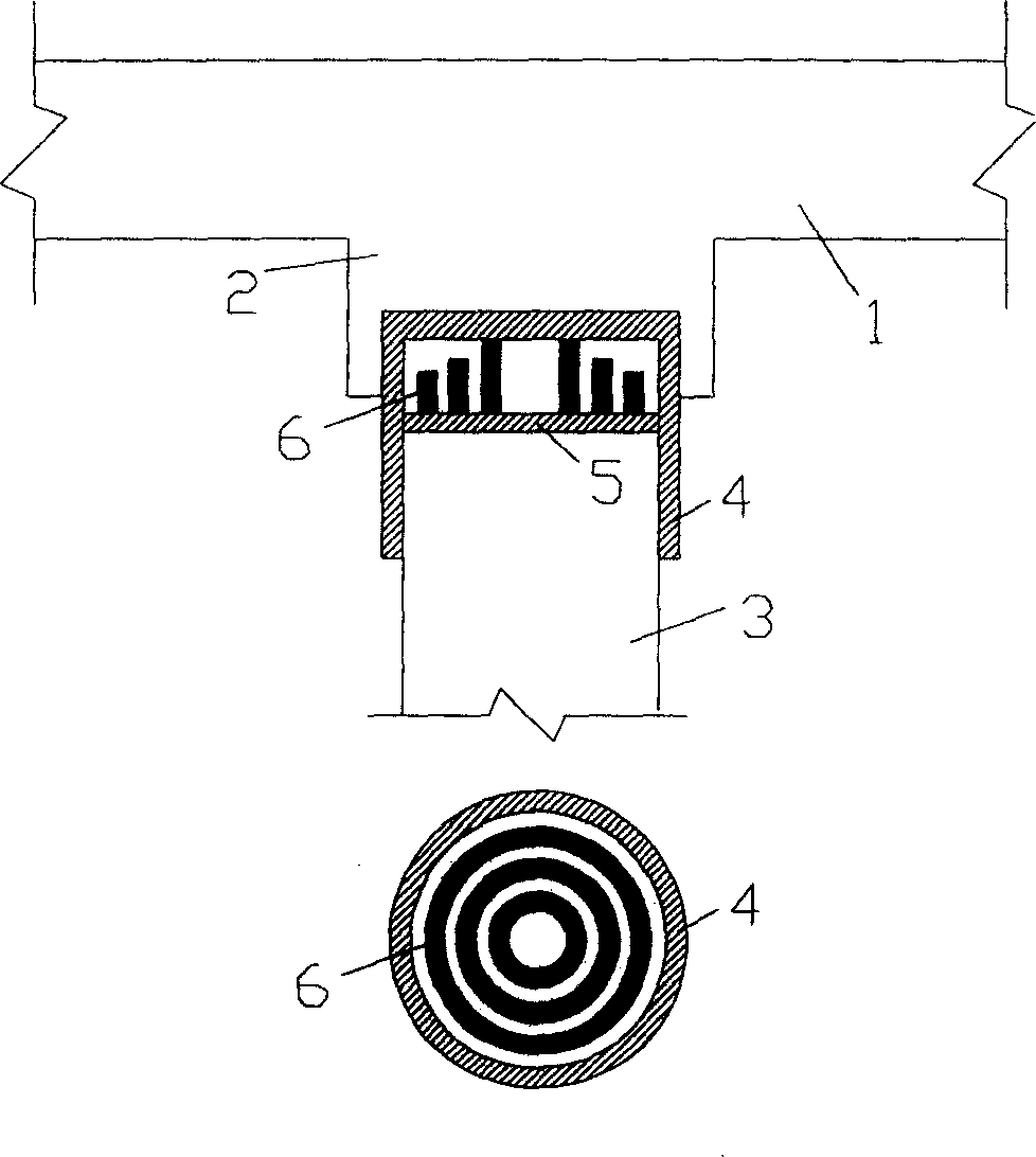
[0020] A pile end displacement adjustment device for adjusting pile end displacement, which is composed of a cylinder body 4, a top plate 5 and a telescopic element, the top plate 5 and the telescopic element are arranged in the cylinder body 4, and the telescopic element is located in In the formed cavity, the telescopic element can adopt a displacement adjustment steel plate standing between the inner end surface of the cylinder body 4 and the top plate 5. The displacement adjustment steel plate is cylindrical and can be composed of cylindrical steel plates 6 with different diameters. Shaped steel plates 6 are nested together in order of diameters from small to large, and the cylindrical steel plates are selected from common HPB235 steel. The height difference and spacing of the steel plates should be 1cm and 2cm respectively, and the number of turns should be about 6 turns. The height of the inner ring steel plate and the thickness of the steel plate can be adjusted accordin...

Embodiment 2

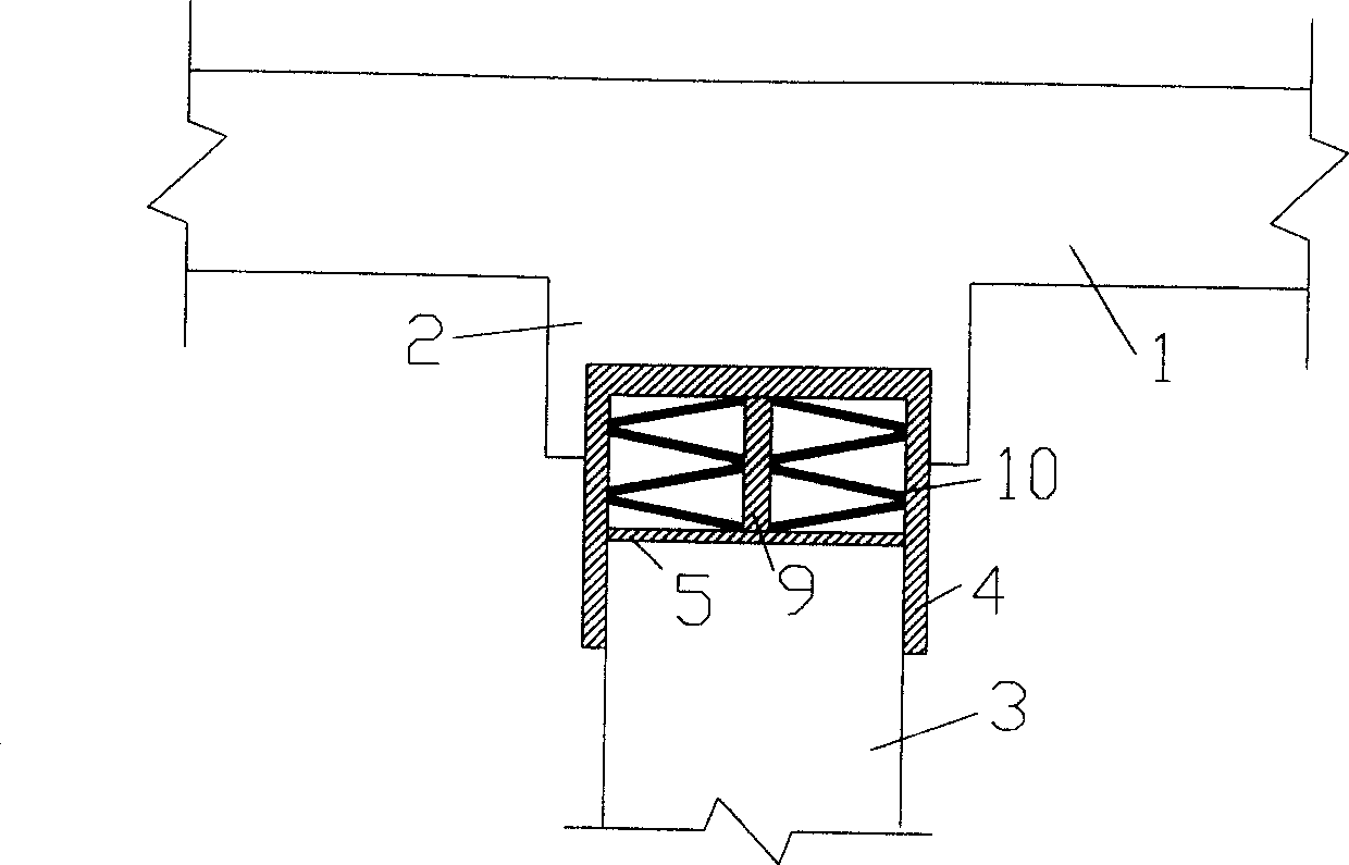
[0022] A pile end displacement adjustment device for adjusting pile end displacement, which is composed of a cylinder body 4, a top plate 5 and a telescopic element, the top plate 5 and the telescopic element are arranged in the cylinder body 4, and the telescopic element is located in In the formed cavity, the telescopic element adopts a disc spring 10, and a central steel column 9 is arranged at the center of the disc spring 10. The above-mentioned disc springs can be directly selected in the disc spring specification table according to the calculated pile support stiffness and displacement adjustment.

Embodiment 3

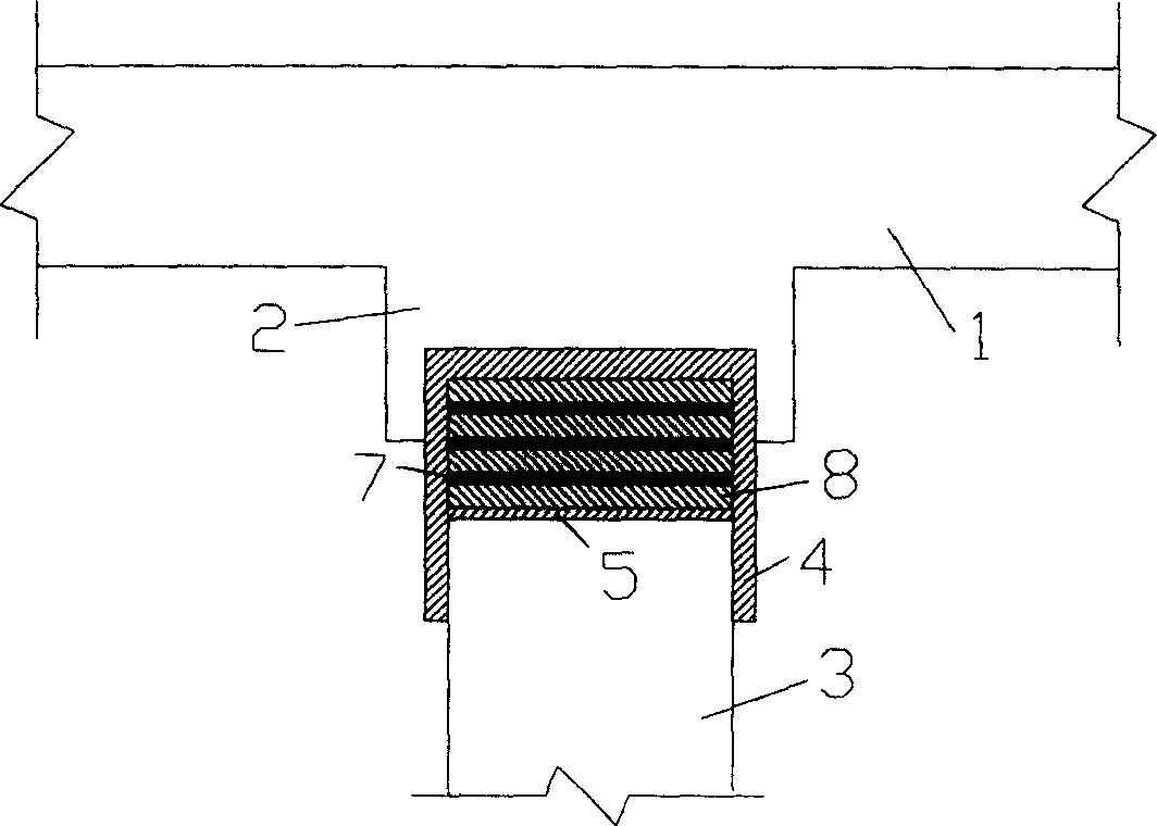
[0024] A pile end displacement adjustment device for adjusting pile end displacement, which is composed of a cylinder body 4, a top plate 5 and a telescopic element, the top plate 5 and the telescopic element are arranged in the cylinder body 4, and the telescopic element is located in In the formed cavity, wherein the telescopic element adopts a rubber pad 8, and more than 2 (such as: 3, 5 or 7 rubber pads) superimposed rubber pads 8 can be used, between adjacent rubber pads There is a steel plate 7 between them, and the above-mentioned rubber pad can use JGD-D type shock-absorbing rubber pad (if rubber pads of other specifications are used, they must meet the corresponding regulations in the "Code for Seismic Design of Buildings" (GB50011-2001)). Its stiffness and thickness can be adjusted as required. Specifically: according to the calculated pile support stiffness, select the corresponding type of rubber pad, and then calculate the height of the rubber pad according to the...


PUM


Abstract

The present invention discloses a kind of installation for adjusting the position of the ground pegs, comprising cylinder body, top plates and expansion and contraction elements. The top plate and the expansion and contraction elements are installed in the cylinder body: and the expansion elements are equipped in the hollow body formed by the expansion elements; the expansion and contraction elements can adopt the movable adjustable steel plates situated between the end of the cylinder body and the top plate. The movable and adjustable steel plates are in cylindrical shape, which can be formed with cylindrical steel plates with different diameters. The cylindrical steel plates are put together serially according to their diameters. The present invention reduces the impact on the variation cost by the subsidence of the composite peg base; after the cylindrical steel plate is used by the expansions and contraction elements, the pressure and deformation of the invention appear in the form of misalignment. After the adjustment of the position accordingly, the load bearing capacity trends to be infinitely great, convenient to adjust the extent of mobility on top of the peg base of the buildings. Ordinary construction materials are used and the structure is simple.

Description

technical field [0001] The invention relates to a device for freely adjusting pile top displacement, in particular to a pile end displacement adjusting device. Background technique [0002] With the gradual development of high-rise buildings, the piled raft foundation has gradually become its main foundation form and has been widely used. [0003] (1) Pile-raft foundations are divided into two types: conventional pile foundations and composite pile foundations in specific applications. [0004] Conventional pile foundations are mainly based on the recommendations of "Code for Design of Foundations" (GB50007-2002) and "Technical Specifications for Building Pile Foundations" (JGJ94-94). 1 / 2 and 1 / 1.65 of the ultimate bearing capacity), regardless of the bearing performance of the soil between the piles, the load of the superstructure is completely borne by the piles. The pile foundation types are mainly end-bearing piles and friction piles according...

Claims


Application Information

Patent Timeline
Patent Type & Authority Applications(China)
IPC IPC(8): E02D35/00
Inventor 宰金珉周峰梅国雄王旭东
Why Eureka
Try Eureka