Supercharge Your Innovation With Domain-Expert AI Agents!

Circuit and method for encoding data and data recorder

A data and circuit technology, applied in the field of product coding and adding, can solve the problems of increased memory power consumption, loss of real-time recording operation, expensive memory, etc., and achieve the effect of reducing the operating clock frequency

Inactive Publication Date: 2005-11-23
SANYO ELECTRIC CO LTD
View PDF1 Cites 0 Cited by
  • Summary
  • Abstract
  • Description
  • Claims
  • Application Information

AI Technical Summary

Problems solved by technology

[0026] However, such high clock frequency memory is expensive
Therefore, when such a memory is mounted on a DVD recorder or the like, there is a problem of cost
In addition, another problem brought about by the high operating clock frequency of the memory is to increase the power consumption of the memory
On the other hand, if the operating clock frequency of the memory is lowered, the encoding cannot be completed on time, causing concerns that the recording operation may lose real-time performance.

Method used


Image

  • Circuit and method for encoding data and data recorder
  • Circuit and method for encoding data and data recorder
  • Circuit and method for encoding data and data recorder

Examples


Embodiment 1

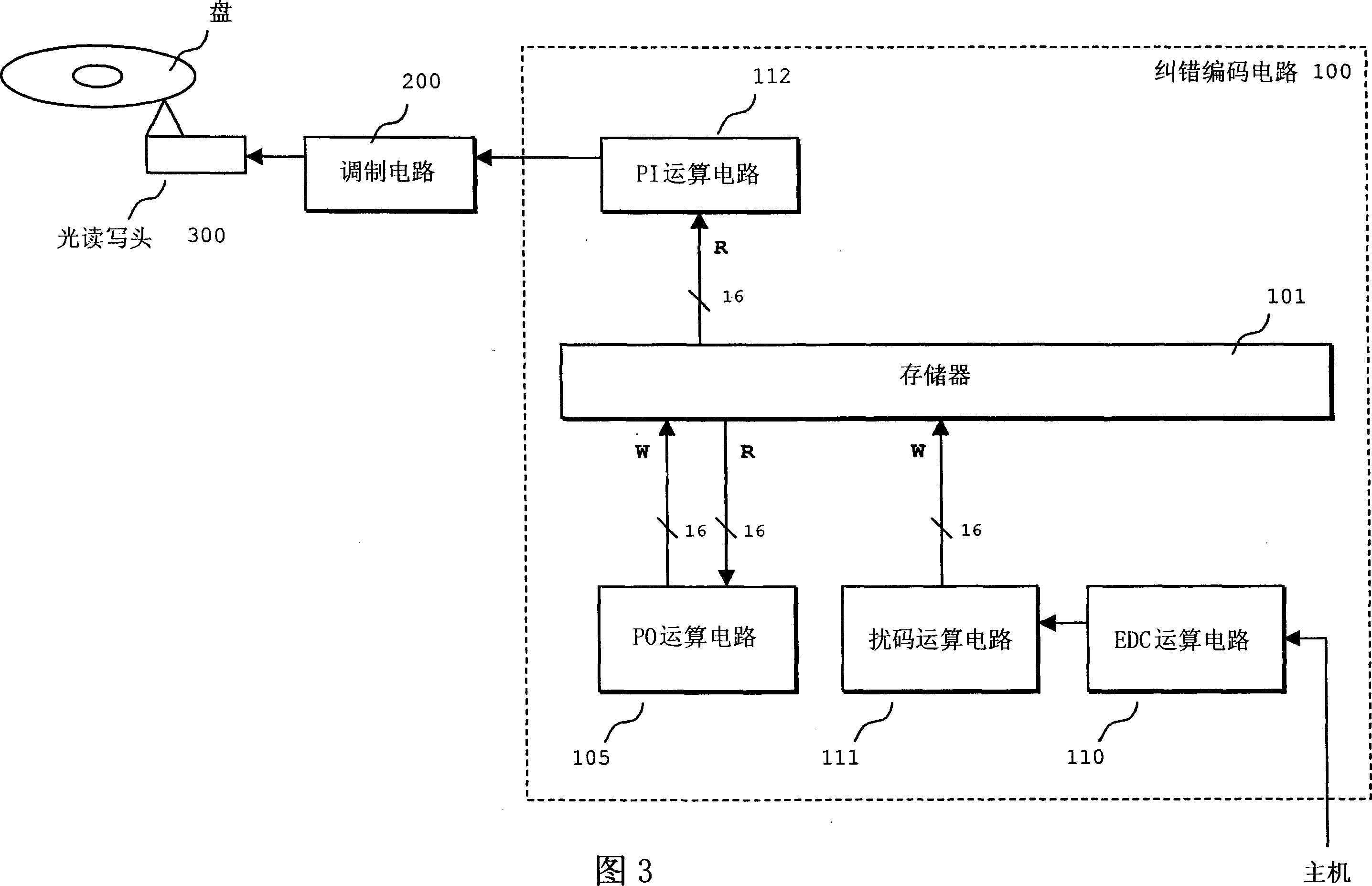
[0056] figure 1 It is an installation diagram of the disc recorder of the first embodiment. which with Figure 7 Similar parts are denoted by the same reference numerals.

[0057] The memory 101 includes SDRAM or the like. The PI operation circuit 104 calculates an error correction code in the PI direction (row direction), and adds it to the scrambled data. The PO operation circuit 105 calculates an error correction code in the PO direction (column direction), and adds it to the scrambled data. The EDC operation unit 110 calculates an error detection code and adds the error correction code to the data. The scramble operation circuit 111 scrambles the data to which the error detection code has been added. The modulation circuit 200 performs predetermined modulation on input data to generate a recording signal. An optical head 300 uses a laser beam corresponding to a recording signal input from the modulation circuit 200 to write data into the optical disc.

[0058] Acco...

Embodiment 2

[0065] By replacing the PI operation circuit 104 with a PI operation circuit 112 as described below, it is possible to further reduce the number of accesses to the memory 101 .

[0066] Figure 3 is a diagram of a setup for this situation. In this setting example, the procedure of PI and PO encoding and the operation of accessing the memory 101 are different from Embodiment 1. In other words, in this setting example, the processing of the PO operation circuit 105 is performed first, and then the PI operation circuit 112 adds the PI code of the line data, after which the data is directly output to the modulation circuit 200 .

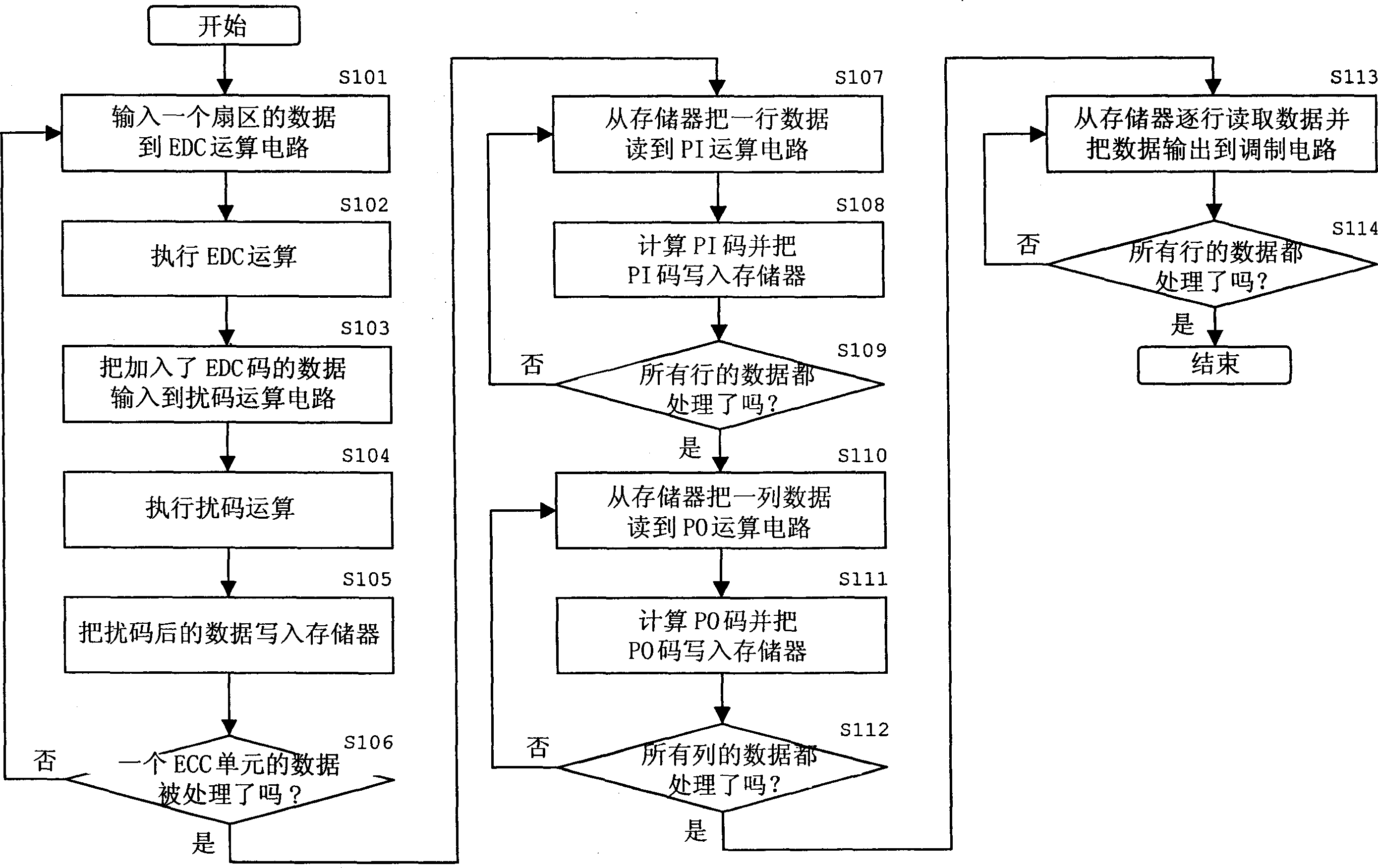
[0067] Figure 4 A flowchart showing the data error correction encoding process for one ECC unit. Steps S101 to S106 are the same as in Embodiment 1.

[0068] In the process of steps S101 to S106, after the data of an ECC unit is written into the memory 101, the data of a column is first read from the memory 101 to the PO operation circuit 105 (S120), ...


PUM


Abstract

To provide a data encoding circuit capable of securing real-timeness of a recording operation even in a memory of a low operation clock frequency by reducing the number of times of accessing the memory, and simultaneously reducing power consumption and memory costs. Prior to its writing in a memory ( 101 ), data from a host is input to an EDC arithmetic operation circuit ( 110 ) and a scrambling arithmetic operation circuit ( 111 ) to be processed, and then the error correction codes are added to the data written in the memory ( 101 ) from the scrambling arithmetic operation circuit ( 111 ) by a PI arithmetic operation circuit ( 104 ) and a PO arithmetic operation circuit ( 105 ). Accordingly, it is possible to omit memory access when the data is written from the host in the memory, and memory access when the data is read from the memory to the EDC arithmetic operation circuit. Thus, it is possible to reduce an operation clock frequency of the memory ( 101 ).

Description

technical field [0001] The present invention relates to a circuit and method for data encoding and data recording, especially, the present invention is suitable for the case where an error correction code is added by product encoding in row (PI) direction and column (PO) direction. Background technique [0002] When data is recorded in a digital versatile disc (DVD), an error correction code is added to each ECC unit. This error correction is performed using product coding. Error correction codes in the row (PI) direction and column (PO) direction are added to each ECC unit distributed in the memory. [0003] Image 6 It shows the structure of an ECC unit with error correction code added. As shown in the figure, one ECC unit includes data of 208 rows and 181 columns. PO codes and PI codes are added to rows 192 to 208 and columns 172 to 181, respectively. Wherein, the PI code is the data added to each row (data forming a sector), and the PO code is the data added to each ...

Claims


Application Information

Patent Timeline
Patent Type & Authority Applications(China)
IPC IPC(8): G11B20/12G11B20/10G11B20/18H03M13/00
CPCG11B20/1866G11B2020/184G11B20/1833
Inventor 冈本实幸夫马正人富泽真一郎野吕聪妹尾秀满
Owner SANYO ELECTRIC CO LTD
Features
  • R&D
  • Intellectual Property
  • Life Sciences
  • Materials
  • Tech Scout
  • Unparalleled Data Quality
  • Higher Quality Content
  • 60% Fewer Hallucinations
Learn More