

Hybrid drive device and automobile with device mounted thereon
一种驱动装置、驱动车轮的技术,应用在传动装置、动力装置、电动汽车等方向,能够解决壳体部件轴心偏移、降低第1电动马达支撑精度、不利单元系列化等问题
- Summary
- Abstract
- Description
- Claims
- Application Information
AI Technical Summary
Problems solved by technology
Method used
Image

Examples
no. 1 Embodiment approach
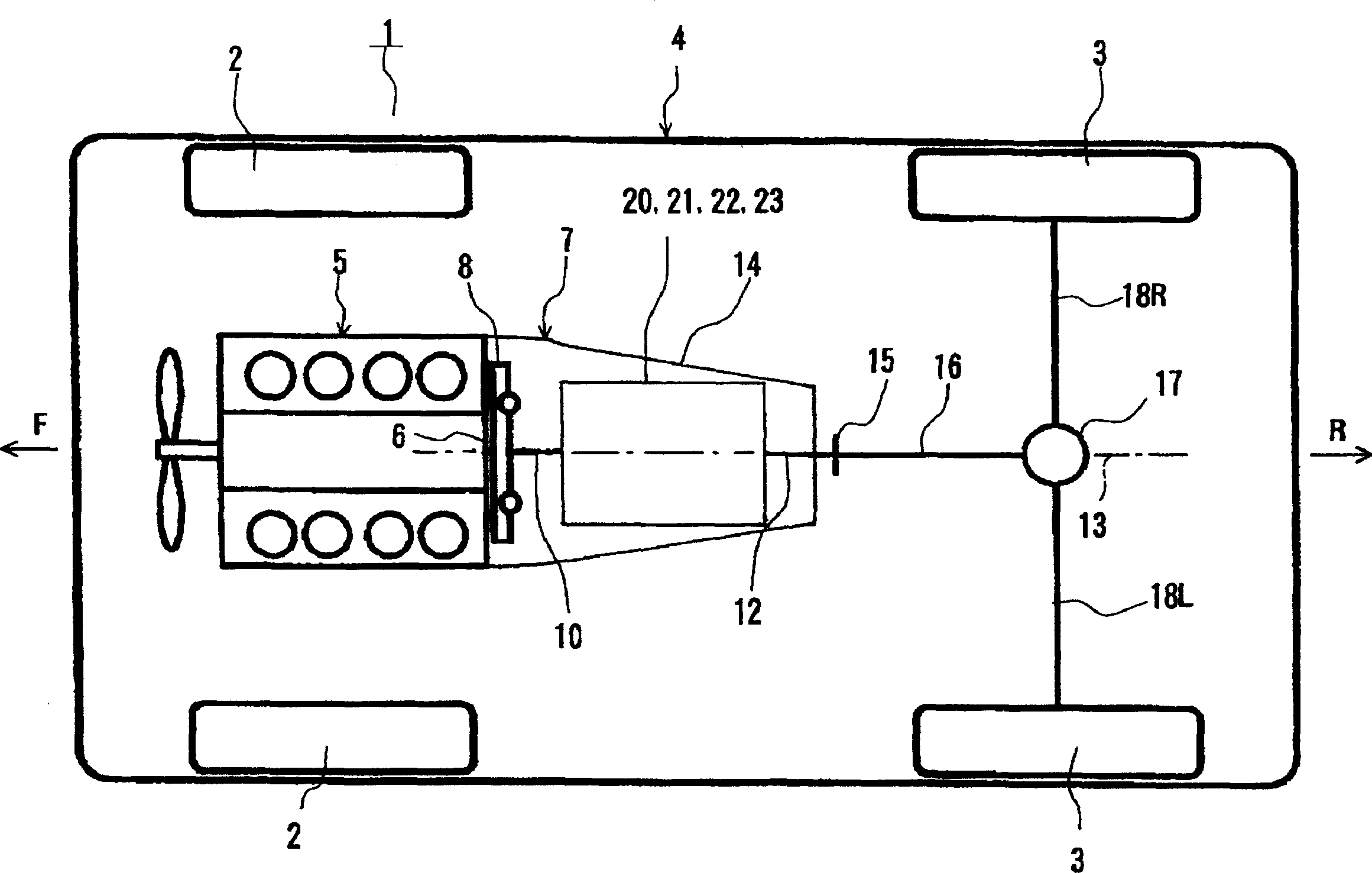
[0071] figure 1 An example of an automobile according to the present invention, that is, an automobile 1 equipped with a hybrid drive device according to the present invention is shown. The car 1 shown in the same figure is a FR (front engine, rear wheel drive) type car, and the same figure is a plan view showing its approximate structure. In addition, in an actual automobile, the arrow F direction in the figure is the front side, and the arrow R direction is the rear side.
[0072] The automobile 1 shown in the figure has a vehicle body 4 supported by left and right front wheels 2, 2 and left and right rear wheels 3, 3 as driving wheels. The internal combustion engine 5 is mounted on the front portion of the vehicle body 4 via a rubber mount (not shown), and a crankshaft 6 serving as an output shaft thereof faces in the front-rear direction. In addition, in the same figure, the output shaft formed by the rear protrusion part of a crankshaft is the crankshaft 6 shown in fig...
no. 2 Embodiment approach
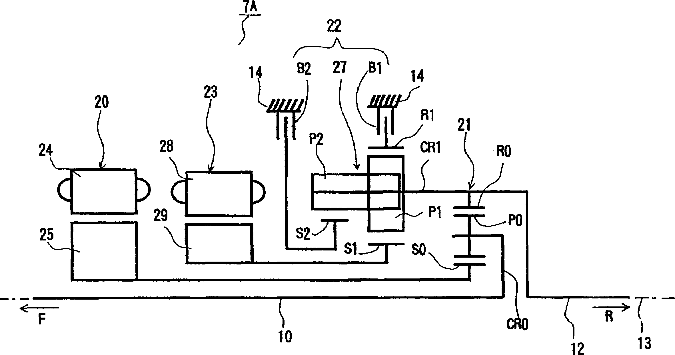
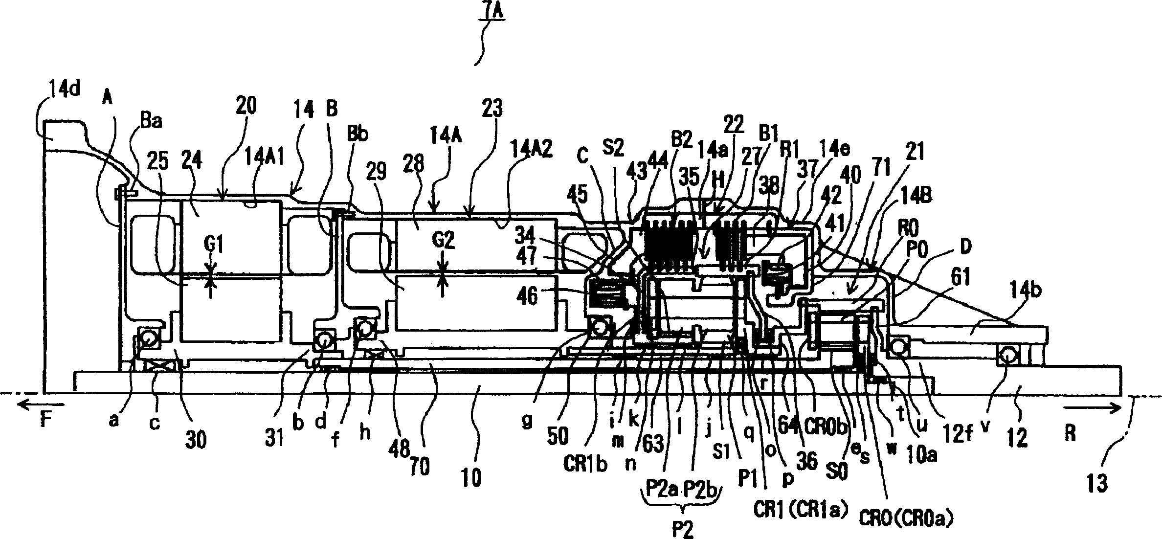
[0139] Next, as a piggyback on figure 1 As another example of the hybrid drive device 7 according to the present invention in the automobile 1 shown, the hybrid drive device 7B according to the present embodiment will be described. First, refer to Figure 7 The skeleton diagram of , illustrating the general situation of the compound drive device 7B as a whole, and then refer to Figure 8 , describe the specific structure in detail. In these figures, the arrow F direction is the front side of the vehicle body (internal combustion engine side), and the arrow R direction is the vehicle body rear side (differential gear side).
[0140] Such as Figure 7 As shown, the compound drive unit 7B moves from close to figure 1 From the internal combustion engine 5 side, that is, from the front side to the rear side, a first electric motor 20, a second electric motor 23, a planetary gear 21 for power distribution, and a speed change device 22 are sequentially arranged. These are acco...
no. 3 Embodiment approach
[0202] Next, as a piggyback on figure 1 An example of the compound drive device 7 relevant to the present invention on the shown automobile 1, with reference to Figure 12 The skeleton diagram of FIG. 2 illustrates the hybrid drive device 7C of this embodiment. In these figures, the arrow F direction is the front side of the vehicle body (internal combustion engine side), and the arrow R direction is the vehicle body rear side (differential gear side).
[0203] Such as Figure 12 As shown, the compound drive unit 7C moves from close to figure 1 From the internal combustion engine 5 side, that is, from the front side to the rear side, a planetary gear 21 for power distribution, a first electric motor 20, a second electric motor 23, and a speed change device 22 are sequentially arranged. These are accommodated in housing part 14 (see figure 1 ) on the inner side of the first axis 13 (around the first axis 13) and arranged in order along the first axis 13. Next, the plane...
PUM
 Abstract
Description
Claims
Application Information