
Magnet field adjustable magnetic separator

A magnetic separator and magnetic field technology, applied in the field of magnetic field adjustable magnetic separator, can solve the problems of background magnetic field loss, inability to balance output and grade, and grade decline.

Inactive Publication Date: 2005-11-30
李文武
View PDF0 Cites 7 Cited by
  • Summary
  • Abstract
  • Description
  • Claims
  • Application Information

AI Technical Summary

Problems solved by technology

Due to the technical limitation, the gap between the inner rotating shaft and the outer cylinder is not less than 10mm, so that the background magnetic field is lost. In order to be suitable, the manufacturer has to adopt a double machine connection, which still cannot achieve the ideal mineral processing standard.
In order to solve this problem, NdFeB magnets are currently used. It does increase the field strength, but due to the high magnetic field, some mixtures will be adsorbed at the same time, which will lead to a decrease in grade. This is a kind of output and grade that cannot be balanced. real problems

Method used

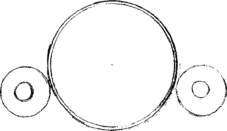
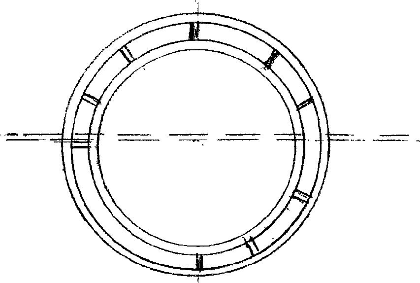

Image

  • Magnet field adjustable magnetic separator
  • Magnet field adjustable magnetic separator
  • Magnet field adjustable magnetic separator

Examples


Embodiment Construction

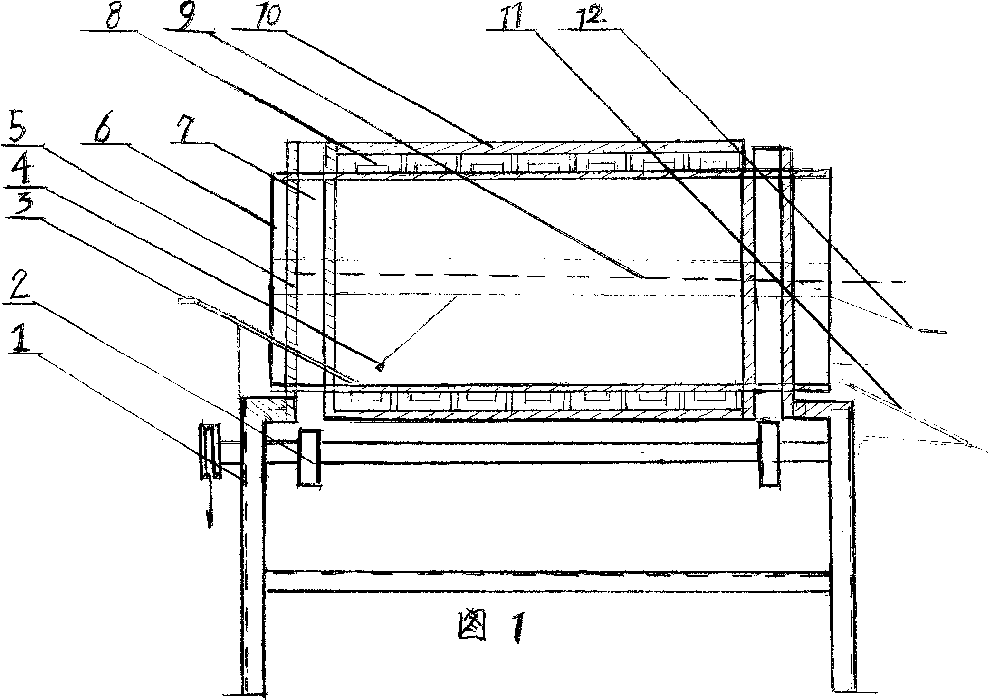
[0009] The adjustable magnetic separator described in Figure 1 includes a stainless steel inner cylinder (6) which is fixed at both ends by a trough-shaped frame (7) and rolls on wheels (2) matched with (7) The shaft end assembly pulley of operation (2) cooperates with the power motor and the reduction gear in the direction indicated by the arrow, and this figure of this part does not provide. The outer part of (6) separates and closes two magnet holders of semicircular type, and the magnetic field effect (6) upper figure number (9) it produces is the non-magnetic zone of this part, and its groove is used for iron powder to come off and discharge here. (9) The dotted line in the middle indicates that the split gap (8) is a permanent magnet, and the figure number (3) is a feeding guide plate (4) is a magnet scraping plate for adsorption. When the raw material enters from (3), it rotates (6) ) continuously absorbs the iron ore and moves forward and flows out on the sand outlet (...


PUM


Abstract

This invention concerns rotation roller type magnetic separator comprised by magnet, whose fix magnetic field can not be adjusted led to conflict that field strengthen is not fit to selected minerals. To match of field strengthen flexibly minerals characters that field strengthen varieties with mineral character and match to take ideal selection, in this invention, reset the received magnetic cylinder inside and ejection magnetic cylinder outside, and the part is switching to adjust magnetic field distance for field strengthen according to need. It is ideal machine to adjust field strengthen any moment.

Description

technical field [0001] The invention relates to a permanent magnetic head assembled in a cylinder for absorbing iron elements. technical background [0002] Current magnetic separators can be divided into two types: water separation type and dry separation type, but most of them still use the fan-shaped bracket internally assembled on the transmission shaft as the magnetic field source. The outside is a stainless steel outer cylinder used to roll off impurities and absorb iron elements. Due to the technical limitation, the gap between the inner rotating shaft and the outer cylinder is not less than 10mm, so that the background magnetic field is lost. In order to be suitable, the manufacturer has to adopt a double machine connection, which still cannot reach the ideal mineral processing standard. In order to solve this problem, NdFeB magnets are currently used. It does increase the field strength, but due to the high magnetic field, some mixtures will be adsorbed at the same...

Claims


Application Information

Patent Timeline
Patent Type & Authority Applications(China)
IPC IPC(8): B03C1/12
Inventor 李文武
Owner 李文武
Learn More