Novel insulated main lead

A technology of insulated busbars and busbars, applied in the direction of insulated cables, insulated conductors, conductors, etc., can solve the problems of high local potential and easy aging of the end insulation layer, and achieve the effects of reducing aging, improving power supply reliability, and extending life

Inactive Publication Date: 2005-11-30
罗志昭
View PDF0 Cites 25 Cited by
  • Summary
  • Abstract
  • Description
  • Claims
  • Application Information

AI Technical Summary

Problems solved by technology

[0003] In order to overcome the concentrated distribution of power lines at the end of the shielding ground la

Method used


Image

  • Novel insulated main lead
  • Novel insulated main lead
  • Novel insulated main lead

Examples


Embodiment Construction

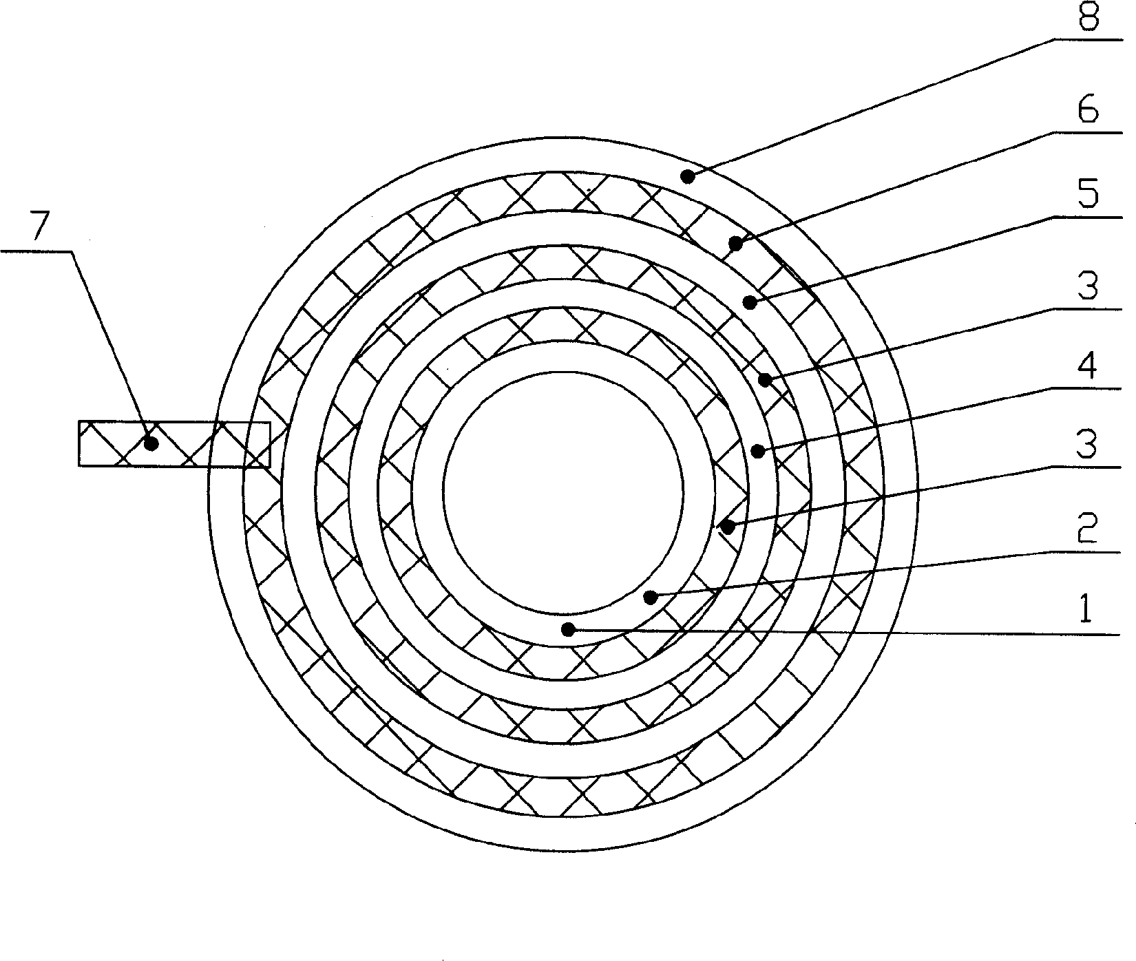
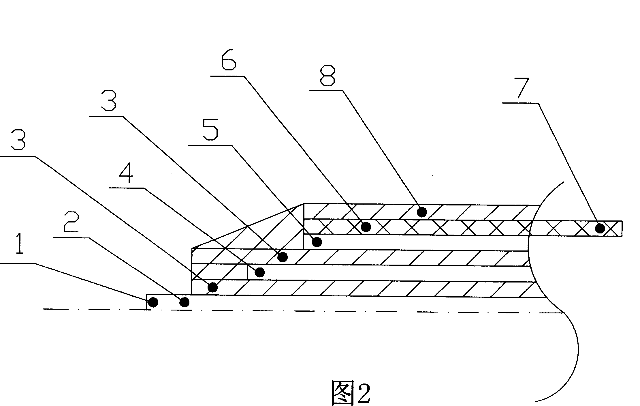
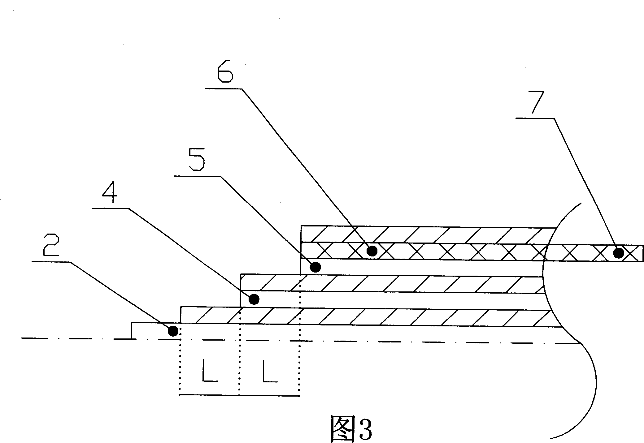
[0011] exist figure 1 Among them, install an insulating layer (3) on the conductor of the copper tube (1), install a metal capacitive screen (4) on the insulating layer (3), install n insulating layers (3) according to the voltage level, and install n insulating layers (3) according to the voltage level. Install n metal capacitive screens (4), without screen, the potential of the ground screen is zero (the ground screen is composed of a semiconductor layer (5) and a conductive metal layer (6), and the ground screen leads to a grounding metal strip (7) for grounding , an insulating sheath layer (8) needs to be installed outside the ground screen for protection of the ground screen.

[0012] In the embodiment shown in Fig. 2, an insulating layer (3) is installed on the copper pipe (1) conductor, a metal capacitive screen (4) is installed on the insulating layer (3), and n insulating layers are installed according to the voltage level (3), add n metal capacitive screens (4) acco...


PUM


Abstract

This invention relates to new isolation generatrix with n pieces of metal electric capacitor screen between isolation layers to make isolation layer lever composed of zero screen, metal capacitor screen, earth screen from high to low and to make each isolation layer with evening voltage protection. The zero screens, n pieces of metal capacitor screens and earth screen take shape of ladder to make the electric lines distributed evenly between metal capacitor screen and earth screen. The generatrix end can avoid over focusing of electric lines free of early aged.

Description

Technical field [0001] The invention relates to a novel insulated busbar, which is especially suitable for high-voltage and high-current transmission, and is safe and reliable in operation. Background technique [0002] At present, the existing substation is used for high-voltage and high-current transmission of insulated busbars. The ground screen of the insulated busbar and the end of the shielded grounding layer are distributed without power lines. The distribution of power lines at the end of the shielded grounding layer is concentrated and the potential is high. The insulation layer at the bottom is easy to age, which reduces the insulation performance and easily causes the busbar to ground short circuit accident. Since the busbar is close to the main transformer, the short circuit of the busbar can easily damage the main transformer and cause a large area of ​​power failure. Contents of the invention [0003] In order to overcome the concentrated distribution of powe...

Claims


Application Information

Patent Timeline
IPC IPC(8): H01B7/00
Inventor 罗志昭
Owner 罗志昭
Why Eureka
Try Eureka