Electrical cable strain relief and electrical closure

A technology for alleviating devices and cables, which is applied in the directions of devices, coupling devices, parts of connecting devices, etc. to relieve stress at wire connections, and can solve problems such as unreliable strain relief devices.

Inactive Publication Date: 2005-12-07
新美亚通讯设备有限公司
View PDF0 Cites 2 Cited by
  • Summary
  • Abstract
  • Description
  • Claims
  • Application Information

AI Technical Summary

Problems solved by technology

There are also cases where crimping a flexible sleeve is an un...

Method used


Image

  • Electrical cable strain relief and electrical closure
  • Electrical cable strain relief and electrical closure
  • Electrical cable strain relief and electrical closure

Examples


Embodiment Construction

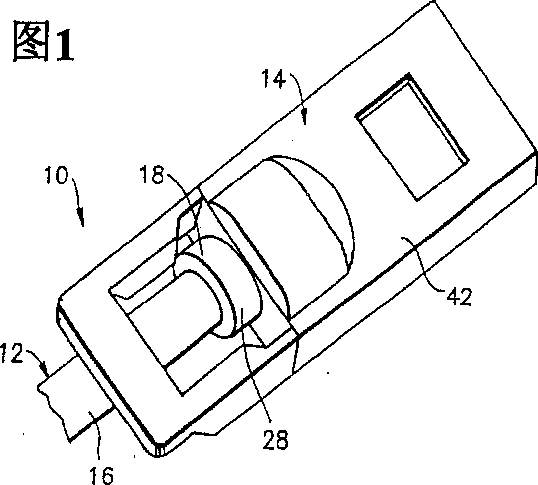
[0019] Referring to Figure 1, there is shown a perspective view of the end of an electrical connector and cable assembly 10 incorporating features of the present invention. While the present invention will be described with reference to the exemplary embodiments shown in the accompanying drawings, it should be understood that the present invention may be embodied in many different embodiments. Furthermore, any suitable size, shape or type of elements, or materials may be used.

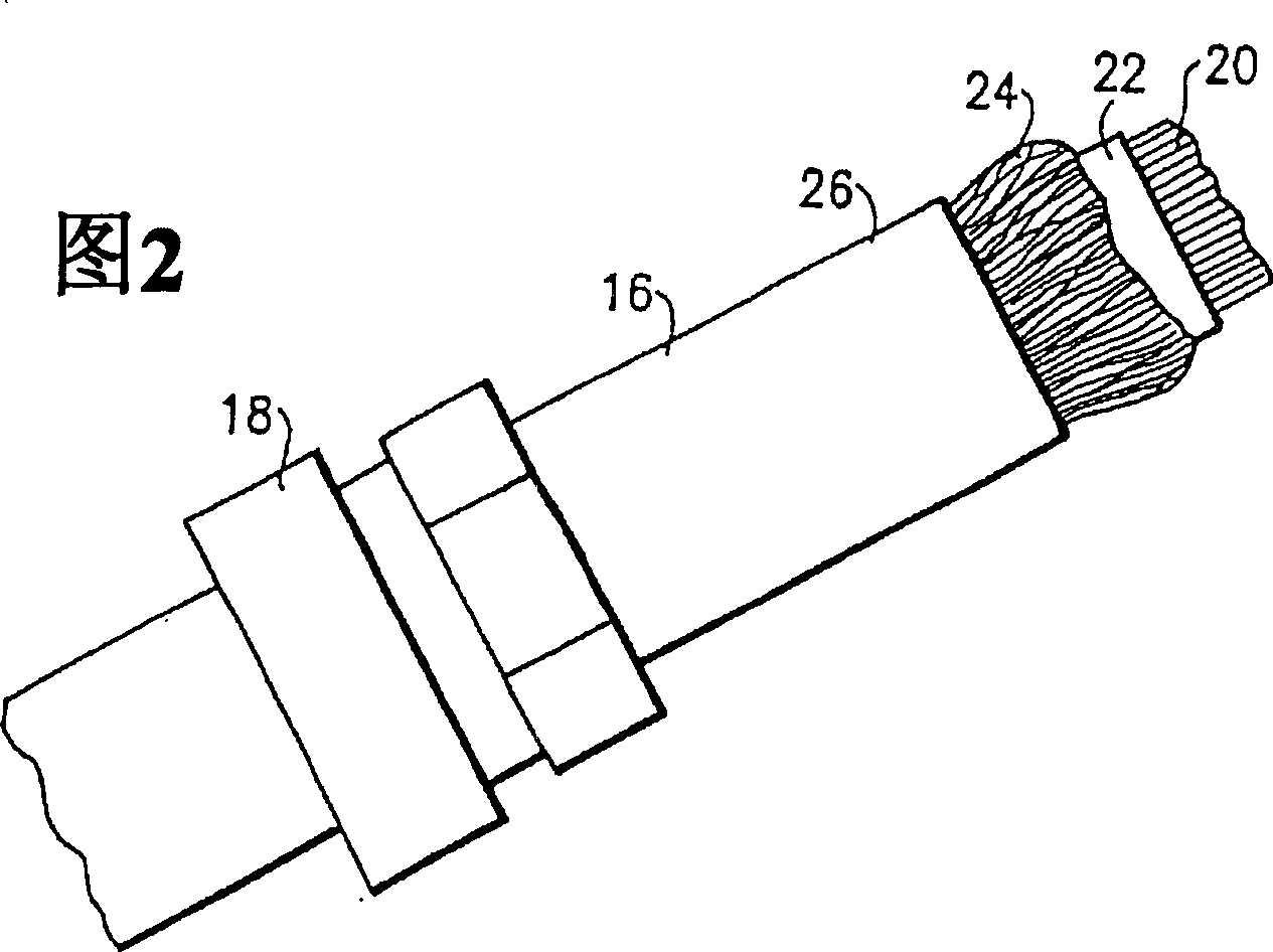
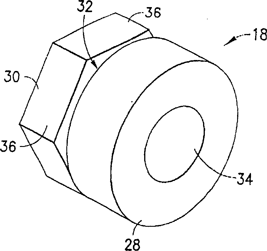
[0020] Strain relief is generally discussed with reference to the integral overformed strain relief 18 shown in Figures 2-6, to which other aspects of the second and preferred embodiments, namely the slip sleeve strain relief 77, 79, 81 will be referred to. Figure 7 to Figure 10 to discuss.

[0021] The electrical connector and cable assembly 10 generally includes an electrical conductor assembly 12 and an electrical connector 14 . Referring still to FIG. 2 , the electrical conductor assembly 12 ge...


PUM


Abstract

Disclosed herein are methods and apparatus for providing as strain relief (18) for use in the assembly of an electrical connector (14) on an end of an electrical conductor (16) having at least an outer braided portion (24), which may be surrounded by an insulating cover. The methods and apparatus disclosed herein provide a low cost approach for installation using minimal tooling, while providing a precise and robust relief that ensures electrical performance.

Description

[0001] This application claims priority to Provisional Patent Application No. 60 / 379,353, filed on May 10, 2002, under Title 35 of the United States Code, 119(e). technical field [0002] The present invention relates to electrical connectors, and more particularly to strain relief devices for use in electrical connectors and conductor assemblies. Background technique [0003] In some conventional electrical connectors and cable assemblies, the most common method for electrically connecting a cable braid to a metal housing is to crimp a metal ferrule over the braid and squeeze slightly when closing the housing. Press the hoop. Usually, crimping is done by hand and therefore imprecise. [0004] This type of system creates a situation where the above-mentioned pair of crimped wires will damage the insulator when too much crimping force is applied. For example, the deterioration of electrical properties is caused by the application of excessive force during crimping. There a...

Claims


Application Information

Patent Timeline
IPC IPC(8): H01R13/655H01R9/03H01R13/58H01R13/648H01R43/00
CPCH01R13/5845H01R9/032H01R13/65912H01R13/648H01R13/58
Inventor 杰弗里·S·辛佩森
Owner 新美亚通讯设备有限公司
Why Eureka
Try Eureka