Light emitting element driving circuit, communication device and light emitting element driving method

A technology for driving circuits and light-emitting elements, which is applied in the layout of electric lamp circuits, circuits, electrical components, etc., can solve the problems of rapid deterioration, short life, and increased power consumption of VCSELs

Inactive Publication Date: 2005-12-14
SEIKO EPSON CORP
View PDF0 Cites 10 Cited by
  • Summary
  • Abstract
  • Description
  • Claims
  • Application Information

AI Technical Summary

Problems solved by technology

Therefore, in the above-mentioned conventional laser drive circuit, there is a problem that the power consumption of the device provided with the VCSEL

Method used


Image

  • Light emitting element driving circuit, communication device and light emitting element driving method
  • Light emitting element driving circuit, communication device and light emitting element driving method
  • Light emitting element driving circuit, communication device and light emitting element driving method

Examples


Embodiment Construction

[0022] Below, with reference to the accompanying drawings, the present invention will be described through the embodiments of the present invention, but the embodiments described below are not intended to limit the content of the present invention described in the claims, and the structures described below are not all of the present invention. Invention is a necessary element for solving technical problems.

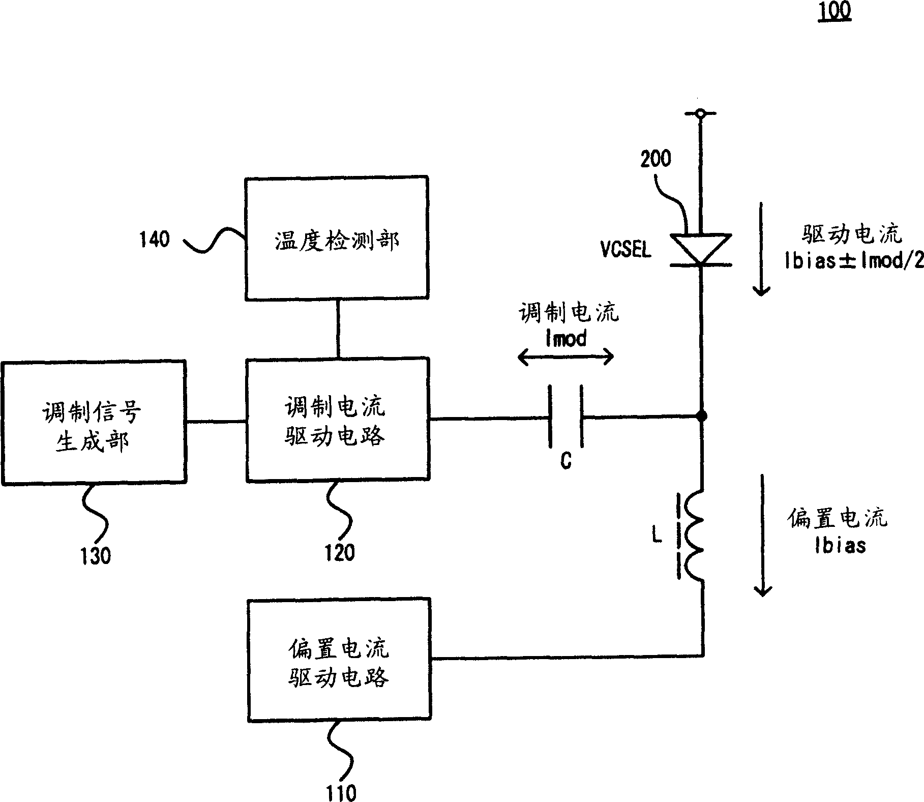
[0023] figure 1 is a schematic diagram of the first embodiment of the light emitting element driving circuit 100 of the present invention. The light emitting element drive circuit 100 includes a bias current drive circuit 110 , a modulation current drive circuit 120 , a modulation signal generation unit 130 , a temperature detection unit 140 , a capacitor C, and a coil L. The surface light-emitting element 200 driven by the light-emitting element driving circuit 100 of this embodiment is preferably a light-emitting element whose threshold current and slope efficiency var...


PUM


Abstract

The invention discloses a light emitting element driving circuit with low power consuming and high reliability. The light emitting element driving circuit drives a surface-emitting element, and includes a bias current driving circuit that supplies a generally constant bias current to the surface-emitting element, a modulation current driving circuit that supplies to the surface-emitting element a modulation current superimposed on the bias current, and a temperature detection circuit that detects the temperature of the surface-emitting element, wherein the modulation current driving circuit decreases the current amount of the modulation current, when the temperature detected rises. The bias current driving circuit may preferably supply the bias current to the surface-emitting element through a coil, and the modulation current driving circuit may preferably supply the modulation current to the surface-emitting element through a capacitor.

Description

technical field [0001] The invention relates to a light-emitting element driving circuit, a communication device and a light-emitting element driving method. In particular, the present invention relates to a light-emitting element drive circuit and a light-emitting element drive method for driving a surface light-emitting element, and a communication device including the circuit. Background technique [0002] A conventional laser drive circuit is disclosed in Non-Patent Document 1 below. The conventional laser drive circuit disclosed in the following Non-Patent Document 1 includes a circuit for generating a bias current and a modulation current (refer to 3-5 in Non-Patent Document 1), and the drive current that superimposes the modulation current and the bias current Provided to VCSEL to drive VCSEL. [0003] The laser drive circuit changes the bias current according to the light emission amount of the VCSEL, and drives the VCSEL so that the light emission amount is substa...

Claims


Application Information

Patent Timeline
IPC IPC(8): H01S5/042H01S5/026H01S5/068H01S5/0683H01S5/18H01S5/183H05B37/02
CPCH01S5/0683H01S5/02296H01S5/183H04B10/564H01S5/0264H01S5/06804H04B10/504H01S5/02257G09G3/30
Inventor 北村升二郎井出次男有竹裕介
Owner SEIKO EPSON CORP
Why Eureka
Try Eureka