Digital analog converting method and system based on pressure-frequency conversion

A voltage-to-frequency conversion and analog-to-digital conversion technology, applied in the field of digital measurement, can solve problems such as the inability to meet the requirements of high-precision measurement and difficulty in compensation

Inactive Publication Date: 2005-12-21
TSINGHUA UNIV
View PDF0 Cites 8 Cited by
  • Summary
  • Abstract
  • Description
  • Claims
  • Application Information

AI Technical Summary

Problems solved by technology

Because this error is related to the amplitude of each signal, it is difficult to compensate
This existing method cannot meet the requirements for high-pr...

Method used


Image

  • Digital analog converting method and system based on pressure-frequency conversion
  • Digital analog converting method and system based on pressure-frequency conversion
  • Digital analog converting method and system based on pressure-frequency conversion

Examples


Embodiment Construction

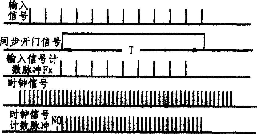
[0076] The first embodiment of the present invention is a sampling rate f s =5kHz analog-to-digital conversion system with optoelectronic isolation. This example uses Figure 6 The circuit structure shown is realized. The input analog voltage signal passes through the voltage-frequency conversion circuit to obtain a digital pulse signal. The input voltage range of the voltage-frequency conversion circuit is from -1 to +1V, and the input voltage is linearly corresponding to the frequency of the output digital pulse signal, and the lower limit of the frequency of the digital pulse signal is f min =10MHz, the frequency upper limit of the digital pulse signal is f max =20MHz. Obviously, f min meet f min >100·f s , f max meet f min max min . The photoelectric isolation circuit composed of optical fiber transmitter, optical fiber, and optical fiber receiver transmits the digital pulse signal to the oversampling counting circuit at the measurement end.

[0077] The clock f...


PUM


Abstract

Through voltage-frequency conversion, the method converts analog voltage to frequency of digital impulse signal linearly. Then, through opto-electronic isolation transmission, electronic jumping number of impulse signal is determined in continuous short time interval. Finally, through filtering and stepping-down frequency obtains A/D conversion of sampled data. The system is composed of voltage-frequency conversion circuit, opto-electronic isolation circuit, counting circuit, digital filtering and stepping-down frequency circuit, and data interface connected in series. Features are: isolated measurement of signal, raised precision of A/D conversion caused by first order oversampling characteristic utilized in counting process, and linear phase characteristic to ensure undistorted sampled wave form.

Description

Technical field: [0001] The invention relates to an analog-to-digital conversion method and system based on voltage-frequency conversion and photoelectric isolation. The method and system can perform voltage-frequency conversion on input analog voltage signals, and then transmit the obtained digital frequency signals to At the measurement end, the sampling data after analog-to-digital conversion are finally obtained through counting and digital filtering down-frequency processing at the measurement end. The invention belongs to the technical field of digital measurement. Background technique: [0002] In the actual engineering site, sometimes the installation point of the measuring probe is far away from the measuring equipment, and the measuring probe is often in a relatively harsh working environment. At this time, it is necessary to adopt the technology of isolation measurement to ensure the accuracy of measurement. For example, in the measurement system of aircraft and...

Claims


Application Information

Patent Timeline
IPC IPC(8): G08C19/36
Inventor 庞浩王赞基
Owner TSINGHUA UNIV
Why Eureka
Try Eureka