
Steady-state controlling method of current parallel voltage compensator for superconductive energy storage

A steady-state control and voltage compensation technology, which is applied to the steady-state control of superconducting current in superconducting applications. In the field of superconducting, it can solve problems such as complex calculations, difficult implementation, and insufficient control accuracy.

Inactive Publication Date: 2006-01-11
TSINGHUA UNIV +1
View PDF0 Cites 3 Cited by
  • Summary
  • Abstract
  • Description
  • Claims
  • Application Information

AI Technical Summary

Problems solved by technology

[0002] At present, there is no same or similar technology as the patent application. The control method proposed in the literature [1] is also applicable to the current parallel voltage compensator based on superconducting energy storage, but this method is complex in calculation and difficult to implement. There are also deficiencies
The method proposed in literature [2] and the patent application are all controlled under the synchronous rotating coordinate system, but this method is only applicable to voltage parallel voltage compensators

Method used


Image

  • Steady-state controlling method of current parallel voltage compensator for superconductive energy storage
  • Steady-state controlling method of current parallel voltage compensator for superconductive energy storage
  • Steady-state controlling method of current parallel voltage compensator for superconductive energy storage

Examples


Embodiment Construction

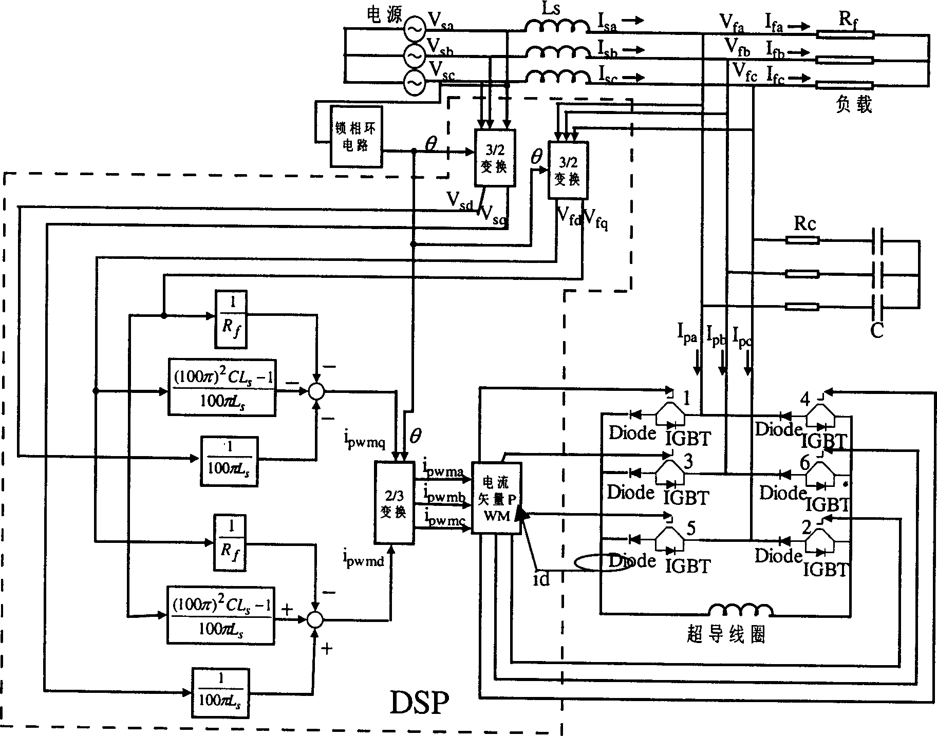
[0084] The working process of the steady state control method is as follows:

[0085] 1. Use the voltage sensor to measure the three-phase voltage Vsa, Vsb, Vsc of the power supply and the three-phase voltage Vfa, Vfb, Vfc of the load, and send the measured voltage to the DSP;

[0086] 2. Perform 3 / 2 transformation on Vsa, Vsb, Vsc and Vfa, Vfb, Vfc in the DSP to obtain the power supply voltage Vsd, Vsq and load voltage Vfd, Vfq in the dq coordinate system;

[0087] 3. In the DSP, use the multiplier and the adder to obtain ipwmd and ipwmq respectively according to formula (1);

[0088] 4. Perform 2 / 3 transformation on ipwmd and ipwmq in DSP, and then use the result of transformation to obtain the driving signals of 6 IGBTs by using the calculation method of current vector PWM;

[0089] 5. The DSP transmits the driving signals of the 6 IGBTs to each IGBT to realize the steady-state control method.

[0090] The program flow chart is attached Figure 4 shown.

[0091] The blo...


PUM


Abstract

This invention relates to a super-conductive current control technology for the current flows through a super-conduction coil when storing energies characterizing that this invention converts a power supply three phase voltage, a load three-phone voltage to ordered stable control current on the d, q shaft by a DSP chip, then converts the ordered current to six control pulses by a current vector pulse width regulator to send them to the grids of transistors in a current transformer composed of correspondingly serial connected six insulation grating bi-polar transistors and six diodes, the input of the current transformer is three-phase load voltage added on three central points of three arms, the output is the super-conduction current flowing through the super-conduction coil connected between the negatives of the three diodes at the end of the three arms and the source of the bi-polar transistor at the start end.

Description

technical field [0001] The invention belongs to the field of superconducting technology, in particular to the technical field of steady-state control of superconducting current in superconducting applications. Background technique [0002] At present, there is no same or similar technology as the patent application. The control method proposed in the literature [1] is also applicable to the current parallel voltage compensator based on superconducting energy storage, but this method is complex in calculation and difficult to implement. There are also deficiencies. The method proposed in literature [2] and the patent application are all controlled under the synchronous rotating coordinate system, but this method is only applicable to voltage parallel voltage compensators. [1] Xun Liu; Xiaoguang Zhu; Xiaohua Jiang. A phasor controls scheme for voltage sag compensation by SMES. Power Electronics and Motion Control Conference, 2004. Vol 2: p882~885 [0003] [2] Takao Kawabata,...

Claims


Application Information

Patent Timeline
IPC IPC(8): H02J3/28H02J15/00
CPCY02E40/67Y02E40/60
Inventor 朱晓光蒋晓华程志光任晓鹏
Owner TSINGHUA UNIV
Learn More