
Channel allocation method

A channel allocation and channel technology, applied in wireless communication, data exchange through path configuration, electrical components, etc., can solve problems such as unstable communication conditions, reduced throughput, and fewer channels

Inactive Publication Date: 2006-01-11
NTT DOCOMO INC
View PDF0 Cites 22 Cited by
  • Summary
  • Abstract
  • Description
  • Claims
  • Application Information

AI Technical Summary

Problems solved by technology

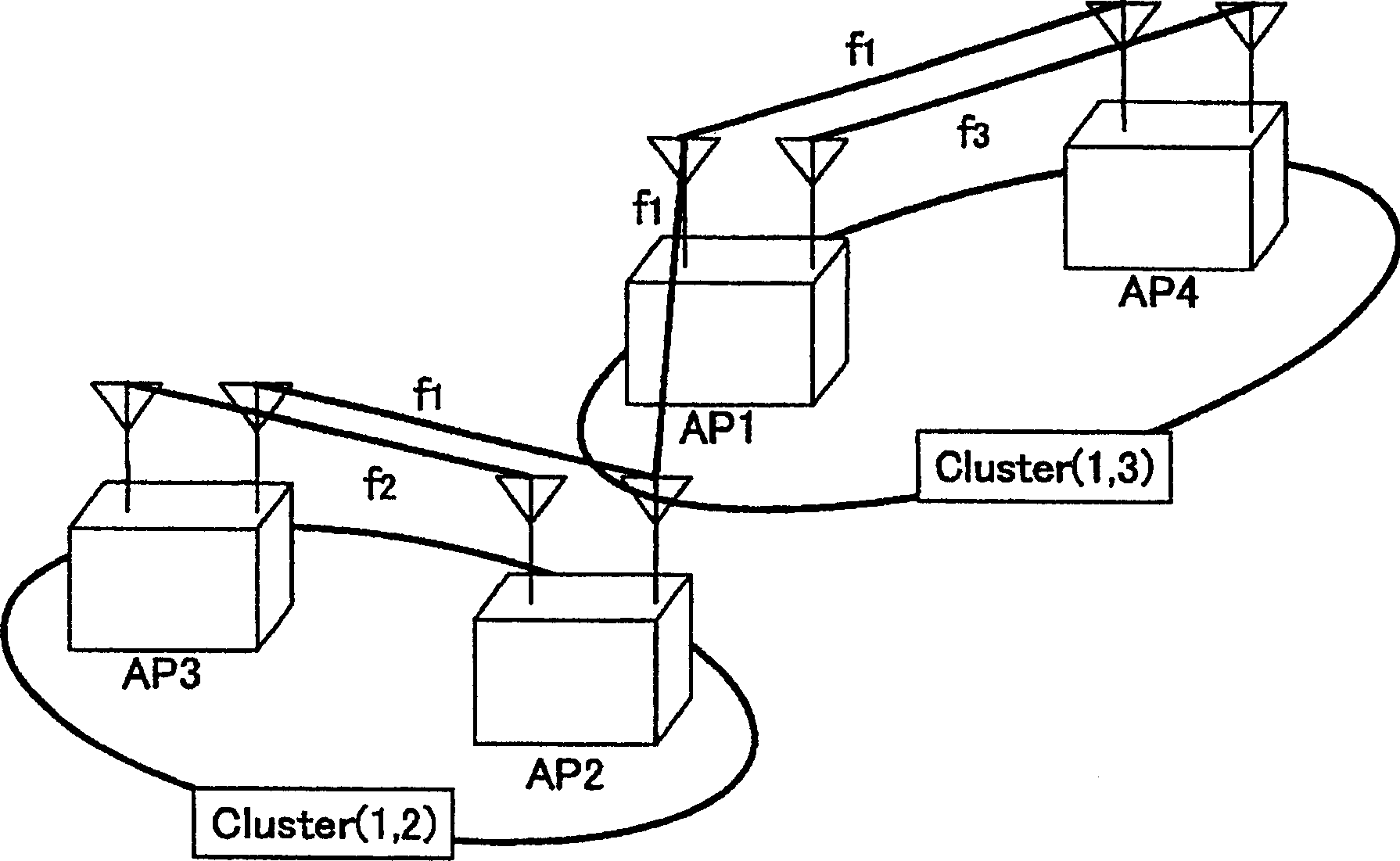
[0010] As mentioned above, in the past, channels were allocated to access points on a mesh network according to the topology, and communication between access points in the same cluster could be performed at high speed because there were many available channels. However, access points across clusters The communication cannot be carried out at high speed due to the small number of available channels
[0011] In this regard, since the communication status in the mesh network is not fixed, but changes according to the current situation, there are many cases where large-capacity communication occurs across clusters. Reasons for Mesh Network Efficiency Deterioration

Method used


Image

  • Channel allocation method
  • Channel allocation method
  • Channel allocation method

Examples


Embodiment Construction

[0043] Hereinafter, preferred embodiments of the present invention will be described with reference to the drawings. In addition, as an embodiment, a case where the present invention is applied to a wireless LAN compliant with IEEE802.11 (Institute of Electrical and Electronics Engineers 802.11) will be described as an example.

[0044] Figure 4 It is a diagram showing a configuration example of an access point to which the channel allocation method of the present invention is applied, and only functional units related to clustering are shown, and other functional units are omitted.

[0045] exist Figure 4 Among them, the access point AP1 has: an intra-node information acquisition unit 1, which acquires its own intra-node information; a statistical information exchange unit 2, which exchanges statistical information with another access point AP2, etc.; a clustering determination unit 3, It judges the node (access point) to be clustered based on the information in the node an...


PUM


Abstract

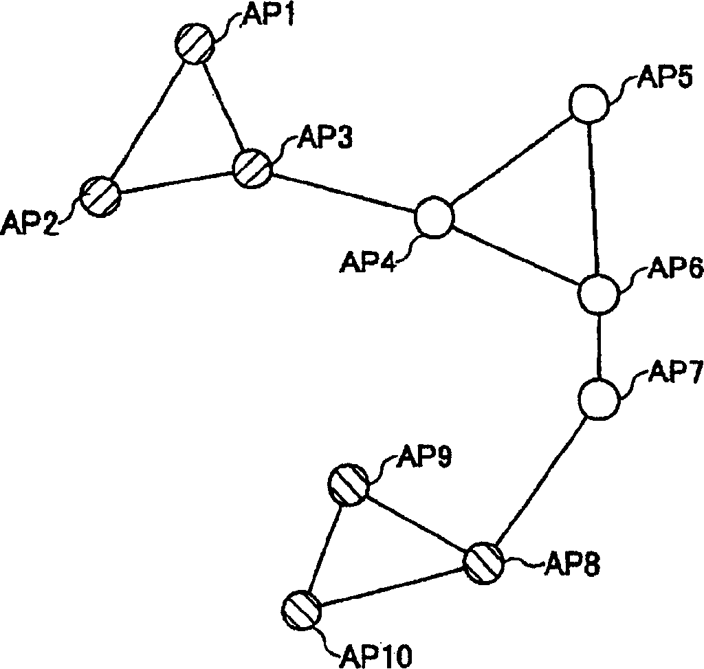
The invention provides a channel allocation method for dynamically allocating channels of a plurality of radio interfaces at each access point included in a mesh network. The method includes the steps of acquiring, at each access point, in-node information about the access point itself, and grouping high-traffic access points in a cluster using a same channel set based on the acquired information.

Description

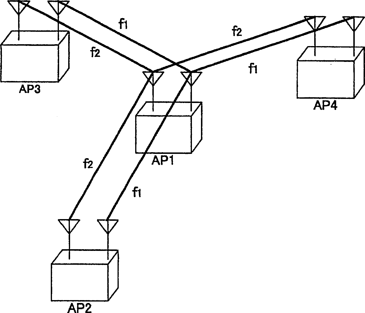
technical field [0001] The present invention relates to a channel allocation method for access points in a mesh network (self-organizing network, autonomous decentralized network) composed of multiple access points with wireless communication functions. Background technique [0002] Considering the widespread use of mesh networks, imagine, for example, the function of setting up access points in TVs, DVD players, etc. at home, without making a connection using cables, etc., and transferring dynamic data from DVD players according to requests from TVs. The purpose of sending image / audio data, etc. to a TV. In order to be able to use this kind of application, it is necessary to increase the speed of data transfer between access points. [0003] figure 1 It is a diagram showing an example of a conventional mesh network provided with the same number of channels as the number of interfaces of the access points. Each of the access points AP1 to AP4 has two interfaces, and channe...

Claims


Application Information

Patent Timeline
Patent Type & Authority Applications(China)
IPC IPC(8): H04Q7/36H04L12/28H04W72/54
Inventor 柳生健吾竹田真二大前浩司青木秀宪藤原淳松本洋一
Owner NTT DOCOMO INC
Learn More