Blowing fan and air conditioner

A technology for blowers and air conditioners, which can be used in air conditioning systems, machines/engines, components of pumping devices for elastic fluids, etc., and can solve problems such as increasing costs

Inactive Publication Date: 2006-01-18
SAMSUNG ELECTRONICS CO LTD
View PDF1 Cites 4 Cited by
  • Summary
  • Abstract
  • Description
  • Claims
  • Application Information

AI Technical Summary

Problems solved by technology

Accordingly, the size-increased cross-flow fan 4 requires a motor 5 that pro...

Method used


Image

  • Blowing fan and air conditioner
  • Blowing fan and air conditioner
  • Blowing fan and air conditioner

Examples


Embodiment Construction

[0026] Reference will now be made in detail to embodiments of the invention shown in the drawings, like reference numerals referring to like parts throughout. Embodiments of the present invention will be described below with reference to the drawings.

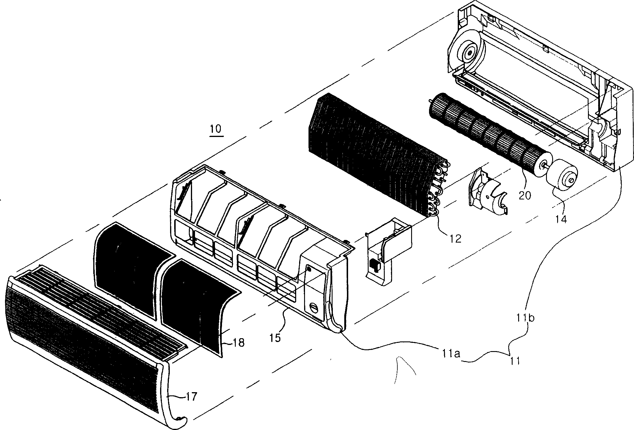
[0027] Such as image 3 As shown in , the air conditioner having an indoor unit 10 according to the present invention includes a heat exchanger 12 disposed in a space formed by a front panel 11a and a rear panel 11b. The heat exchanger 12 exchanges heat between refrigerant circulated according to a refrigeration cycle and indoor air. The blower device for assisting the above-mentioned heat exchange includes a blower 20 and a motor 14 .

[0028] A filter 18 and a suction grill 17 are installed to the front surface of the front panel 11a, and an outlet 15 is formed through a lower portion of the front panel 11a. Accordingly, when the air blower is driven, the air sucked into the indoor unit 10 through the suction grill 17 pass...


PUM


Abstract

The invention discloses a fan assembly comprising a rotatably mounted cross flow fan for blowing air in a direction substantially perpendicular to the axis of rotation of the cross flow fan, blowing members associated with the cross flow fan operable to blow air in an axial direction towards each end of the cross flow fan.

Description

technical field [0001] The present invention relates to a blower and an air conditioner having the same, and more particularly, to a blower for assisting heat exchange between a heat exchanger and outdoor air and an air conditioner having the same. Background technique [0002] In general, an air conditioner is a device for maintaining temperature, humidity, and cleanliness of indoor air suitable for indoor purposes and removing dust and toxic gases from the indoor. The air conditioner is mainly used to constantly maintain the proper state of the room in all seasons, and especially to cool the room in summer and heat the room in winter. [0003] Generally, the air conditioner includes an outdoor unit installed outdoors and an indoor unit installed indoors. Japanese Patent Laid-Open Publication No. 2001-201078 discloses an indoor unit of a conventional air conditioner. Such as figure 2 As shown in , such an indoor unit includes a heat exchanger (not shown) housed in a casi...

Claims


Application Information

Patent Timeline
IPC IPC(8): F24F1/00F24F1/0063F24F7/007
CPCF24F1/0033F24F1/0029F24F2001/0048F04D17/025F24F1/0025F04D17/04F24F7/007F24F1/0007F24F1/0057F24F1/0063F24F1/00F04D29/38
Inventor 罗善旭尹泰锡李俊和
Owner SAMSUNG ELECTRONICS CO LTD
Why Eureka
Try Eureka