An LED illuminating circuit

A technology of light-emitting diodes and lighting circuits, applied to lighting devices, lamp circuit layout, light sources, etc., to achieve the effects of ensuring stability, low cost, and easy implementation

Inactive Publication Date: 2006-01-18
吕大明
View PDF0 Cites 20 Cited by
  • Summary
  • Abstract
  • Description
  • Claims
  • Application Information

AI Technical Summary

Problems solved by technology

Both schemes involve a common technical problem: make the output current conform to the working conditions of the light-emitting diode, and maintain a certain stability
As far as the applicant knows, there are few disclosures and applications of light-emitting diode circuit solutions for daily lighting

Method used


Image

  • An LED illuminating circuit
  • An LED illuminating circuit
  • An LED illuminating circuit

Examples


Embodiment 1

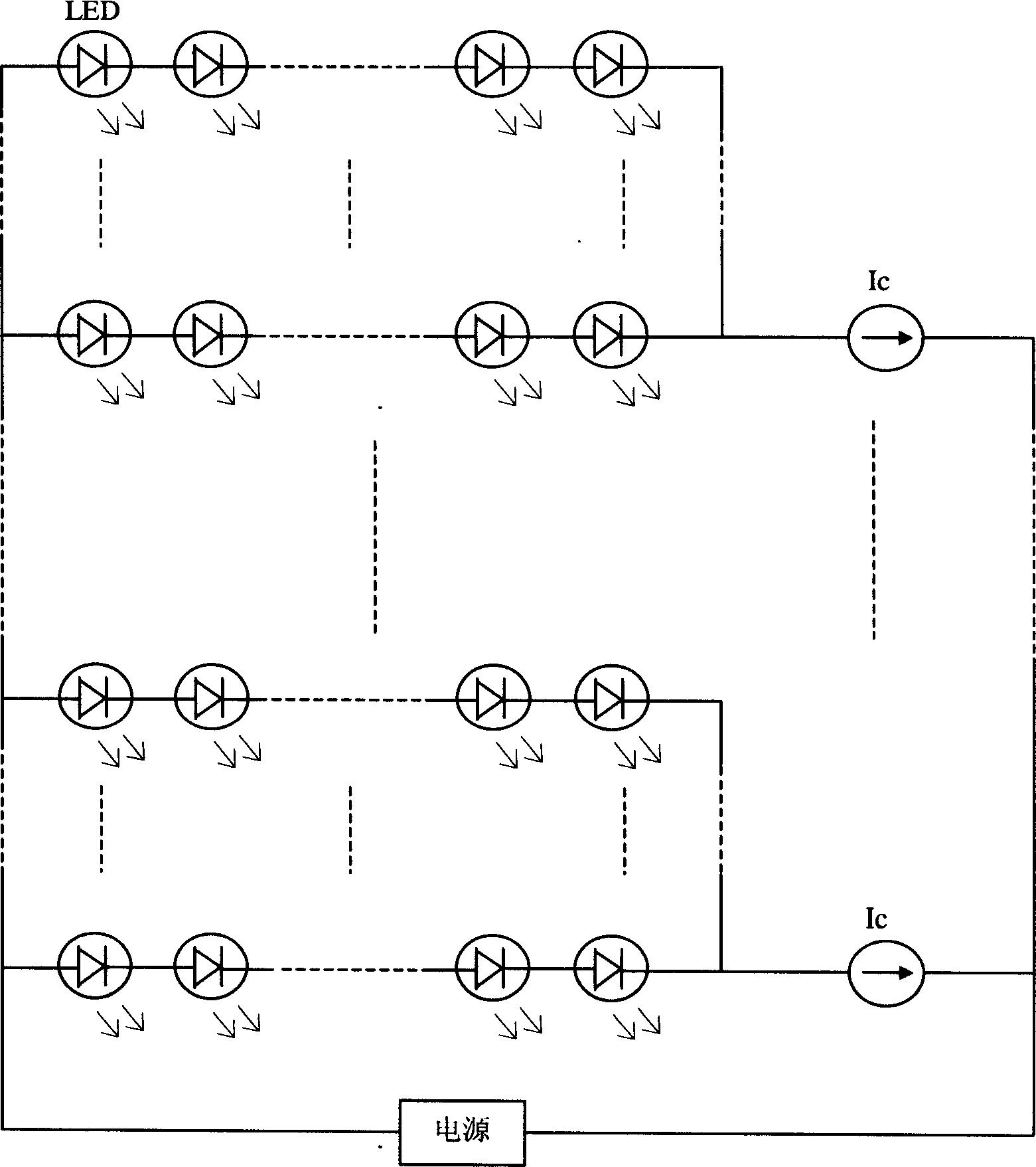
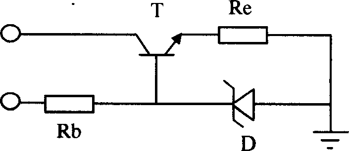
[0018] Embodiment 1. A light-emitting diode lighting circuit, combined with figure 1 , figure 2 and Figure 4 A light-emitting diode array composed of several light-emitting diodes LEDs is connected in series with the constant current source circuit Ic to form the basic circuit of the present invention, and one such basic circuit or several such basic circuits are connected in parallel at both ends of the power supply. Ic in this example uses figure 2 The structure in: a triode T used as a drive current regulating tube, its collector is a constant current output terminal, its base is connected in series with a Zener diode D, and a current-limiting feedback resistor Re is connected in series with the emitter, and then connected in parallel as an external power supply terminal , the base of which is connected in series with a base bias resistor Rb as the base bias voltage input terminal. The power supply in this example uses Figure 4 The structure in: a rectifier bridge Q...

Embodiment 2

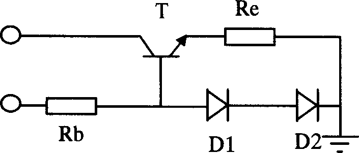
[0019] Embodiment 2, another light-emitting diode lighting circuit, combined with figure 1 , image 3 and Figure 5 , the constant current source circuit and the power supply in Example 1 are respectively used image 3 and Figure 5 to replace the structure in . That is, replace D in Embodiment 1 with two diodes D1 and D2 connected in series, and connect a capacitor C between the two ends of the output port of the rectifier bridge, and keep other structures unchanged.

[0020] In addition, you can combine figure 1 , image 3 , Figure 4 or figure 1 , figure 2 , Figure 5 To obtain a new embodiment, no more details. For the selection of the above-mentioned different constant current sources and rectification circuit schemes: figure 2 The scheme can provide a very stable reference voltage due to the use of Zener diodes, which is relatively image 3 The scheme has a better constant current effect; image 3 The scheme can choose a wide reference voltage range due to...

Embodiment 3

[0021] Embodiment 3, yet another light-emitting diode lighting circuit, combined with Figure 6 , The AC 220V mains power supply AC is connected to a pair of non-adjacent connection points of a rectifier bridge Q composed of four diodes, and the other pair of connection points of Q is connected to a capacitor C for improving the waveform. n high-brightness white light-emitting diodes LED-i (1≤i≤n) are connected in series in a row, one end is connected to one end of capacitor C, the other end is connected to the collector of triode T, and the emitter of T is connected in series with a current-limiting feedback resistor Re. Two diodes D1 and D2 are connected in series with the base of T, and then capacitor C is not connected to one end of the LED row. The base of T is connected in series with a base bias resistor Rb, and then connected to two adjacent LEDs in the LED row. between the diodes. In this example, the model of the four diodes forming Q is IN4007, C is 224P / 400VDC, T ...


PUM


Abstract

This invention discloses a light-emitting diode lighting circuit, which comprises light-emitting diode array and the constant current source circuit, characterized in that it will decrease the stability requirement of the power through the current stabilization function of the constant current source, by which it need not use high energy consumption current-limiting resistance when connecting direct current power supply; when connecting alternating current power, it makes the light-emitting diode working normally only need to use the simple electric rectification scheme. The invention also discloses a circuit made of discrete component, which can realize constant-current and alternating current rectification scheme.

Description

technical field [0001] The invention relates to a lighting circuit, in particular to a light emitting diode lighting circuit. Background technique [0002] At present, the light-emitting devices commonly used in the lighting field mainly include incandescent lamps and fluorescent lamps. Incandescent lamps have been gradually eliminated due to their large heat generation and high energy consumption, while fluorescent lamps have the disadvantages of short life and complicated structure, so the use cost is relatively high. Light-emitting diodes have been paid more and more attention in the field of lighting due to their advantages of high efficiency, energy saving, and long life. [0003] Generally, there are two power supply schemes for driving circuits using light-emitting diodes: one is to use ready-made DC regulated power supplies (such as batteries, accumulators, etc.) to directly supply power to light-emitting diodes; city ​​grid) to power the LEDs. Both schemes involv...

Claims


Application Information

Patent Timeline
Patent Type & Authority Applications(China)
IPC IPC(8): H05B37/02H05B37/00
Inventor 吕舟吕大明
Owner 吕大明
Why Eureka
Try Eureka