Switch test device and switch test equipment

A test device and switch technology, applied in the direction of data exchange network, digital transmission system, electrical components, etc., can solve the problems that cannot meet the test requirements of Ethernet switches, single flow test or power supply efficiency test, etc.

Active Publication Date: 2006-01-25
NEW H3C TECH CO LTD
View PDF0 Cites 14 Cited by
  • Summary
  • Abstract
  • Description
  • Claims
  • Application Information

AI Technical Summary

Problems solved by technology

[0007] The purpose of the present invention is to provide a switch test device and switch test equipment to solve the existing technical problems that can only provide a single flow test or power supply efficiency test and cannot meet the test requirements of Ethernet switches with POE functions

Method used


Image

  • Switch test device and switch test equipment
  • Switch test device and switch test equipment
  • Switch test device and switch test equipment

Examples


Embodiment Construction

[0028] The present invention will be described in detail below in conjunction with the accompanying drawings.

[0029] Since the signal output by the port of the switch is a combined signal of the current signal and the Ethernet data signal, when testing each port of the switch, it is necessary to separate the current signal and the Ethernet data signal from each other, and then test the current signal. Validity detection and data exchange capability test for Ethernet data signals.

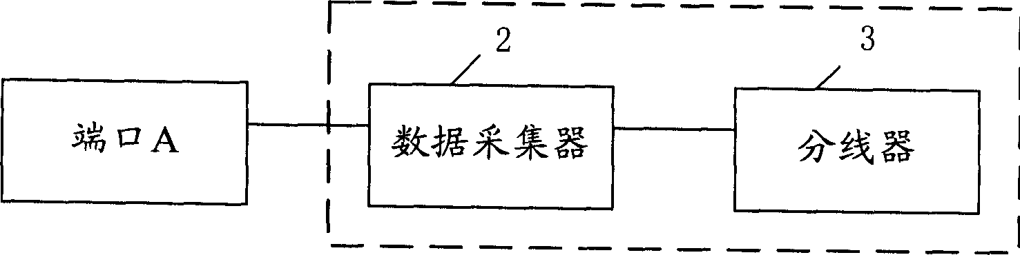
[0030] see image 3 , which is a schematic structural diagram of a switch testing device provided by the present invention. It is mainly used to test a port (such as port A) of a switch with the power-over-Ethernet function. It includes data collector 2 and splitter 3, where:

[0031] Splitter 3: Connect the port (port A) that needs to be detected in the switch and the data collector 2 to separate the current signal and the Ethernet data signal from the composite signal output from port A, and ...


PUM


Abstract

A test device of switch consists of data collector and de-concentrator which connecting port needed test and data collector in the switch and separating current signal and Ethernet data signal from signal of port output, sending Ethernet data signal to data collector and detecting whether current signal is effective or not. The data collector detects data switching ability of received Ethernet data signal. A test equipment enabling to test multiple ports of switch at one time is also disclosed .

Description

technical field [0001] The present invention relates to the field of switch testing, in particular to a switch testing device and switch testing equipment for testing a switch, in particular to a switch testing device and a testing device for testing a switch with a POE (Power Over Ethernet, Power Over Ethernet) function. Switch test equipment. Background technique [0002] Traditional Ethernet switches only need to transmit Ethernet data signals externally. Therefore, when testing a traditional Ethernet switch, it is usually only necessary to detect the data exchange capability of the Ethernet switch. At present, the most widely used Ethernet switch detection device is a data collector (sartbits). see figure 1 , which is a schematic diagram of detecting the data exchange capability of a certain port of a traditional Ethernet switch. Port A of Ethernet switch 1 is connected to data collector 2. For example, the output pin of port A is connected to the input pin of data c...

Claims


Application Information

Patent Timeline
Patent Type & Authority Applications(China)
IPC IPC(8): H04L12/26
Inventor 马梁洪建明沈明
Owner NEW H3C TECH CO LTD
Why Eureka
Try Eureka