Composite switching array and branching apparatus testing method therewith

A switch array, composite technology, applied in electrical switches, circuits, digital transmission systems, etc., can solve the problems of bit error testing, low efficiency, difficult to improve test efficiency, etc., and achieve the effect of rapid testing

Active Publication Date: 2005-02-23
ZTE CORP
View PDF1 Cites 8 Cited by
  • Summary
  • Abstract
  • Description
  • Claims
  • Application Information

AI Technical Summary

Problems solved by technology

[0006] 1. If figure 1 As shown, the error test equipment is connected to each branch separately, and each branch can be tested separately, so that it can be judged whether each branch is normal, but since each branch needs to be tested separately, the efficiency is very low
[0007] 2. If figure 2 As shown, connect the bit error test equipment to the sending and receiving ends of the first and last branches, connect the receiving and sending ends of adjacent branches with wires, and directly cascade the test for multiple branches, so that if all the branches are intact , each branch of the branch device can be judged to be normal with only one test, but if some branches of the branch device are faulty, it is necessary to locate the faulty branch according to the method described in method 1, and it is difficult to improve the test efficiency
However, the above method has obvious defects in the case of a large number of branches, because the daisy chain switch matrix and the corresponding test method use the bypass branch method to locate the faulty branch. In the case of a large number, this method will cause the signal sent from the bit error test equipment to pass through more relay nodes, which will cause serious distortion of the signal and even bit errors, so that the test cannot be carried out, and the tested support cannot be tested. Road equipment for fault location

Method used


Image

  • Composite switching array and branching apparatus testing method therewith
  • Composite switching array and branching apparatus testing method therewith
  • Composite switching array and branching apparatus testing method therewith

Examples


Embodiment Construction

[0025] The present invention will be further described in detail below in conjunction with the accompanying drawings and embodiments.

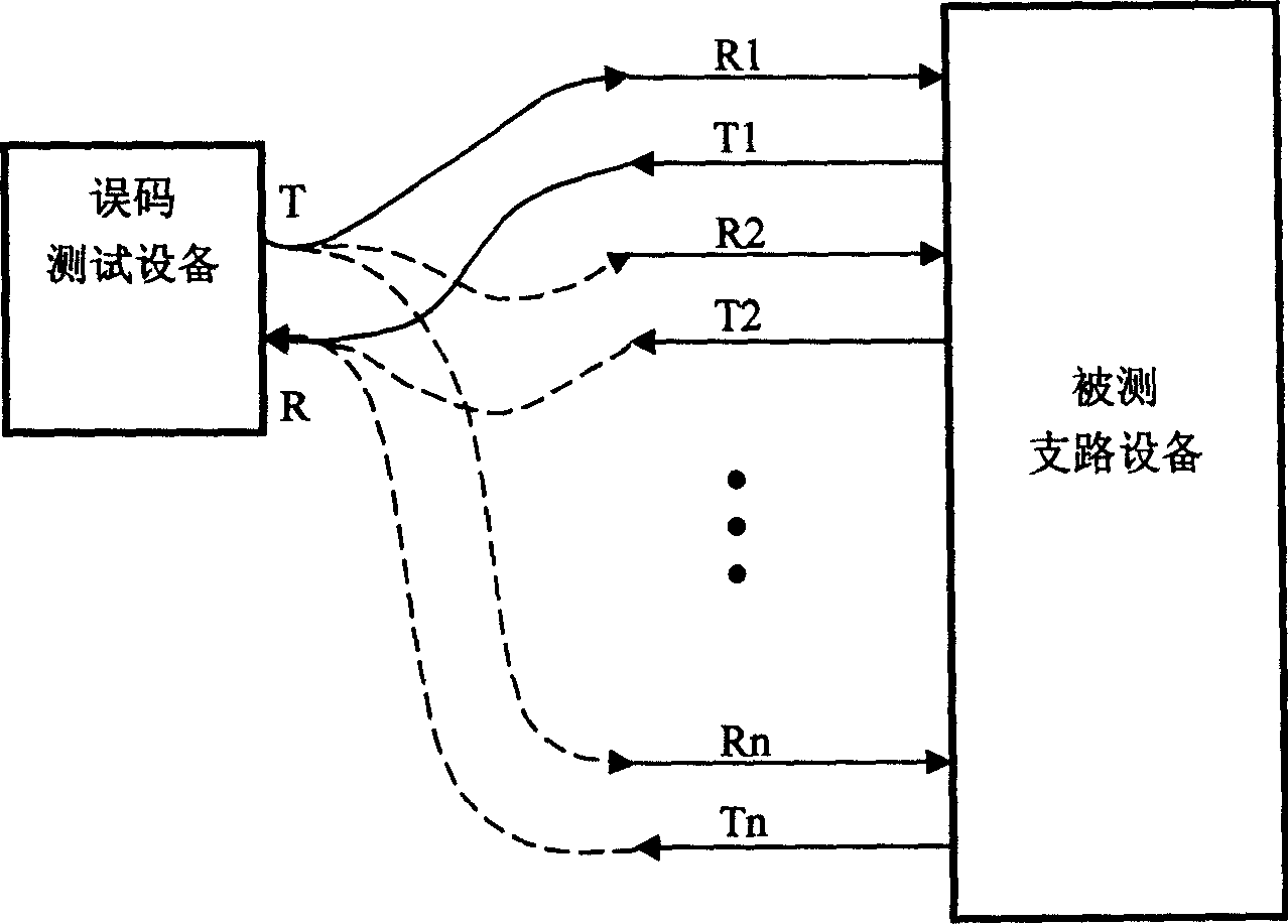
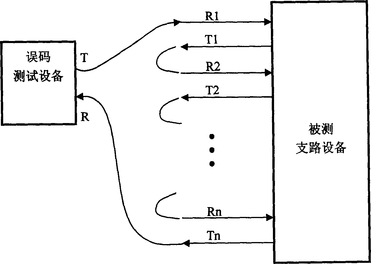
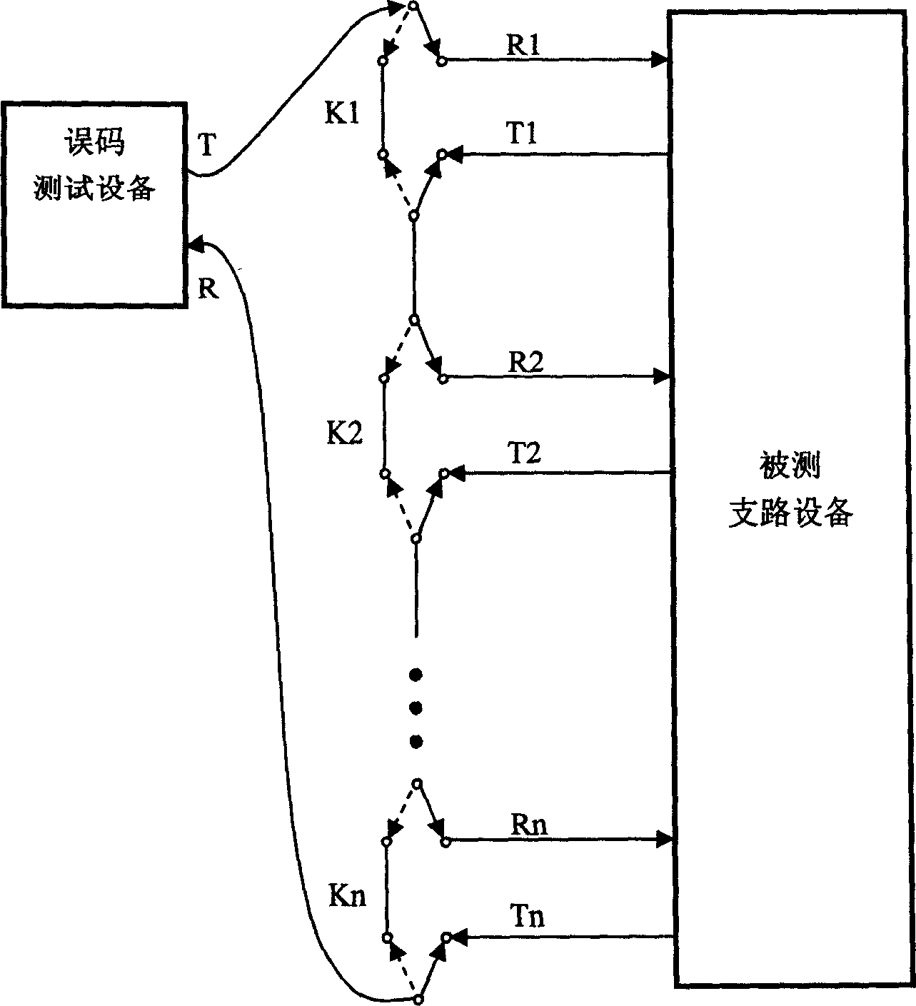
[0026] figure 1 , figure 2 and image 3 The test method shown has been described in detail in the background art.

[0027] Figure 4 It is a structural diagram of the test system of the branch circuit equipment involved in the present invention. Such as Figure 4 As shown, the test system is composed of a bit error test device, a switch array, a tested branch device, and a cross-connect device. The bit error testing equipment sends out test signals and receives the signals from the branch equipment to judge the bit error of the received signal; the switch array connects the bit error testing equipment and the tested branch equipment; the function of the cross-connection equipment is to realize the tested The loopback of each branch signal of the branch device enables the signal received by each branch to be sent from the sending end of ...


PUM


Abstract

The method includes following steps: the complex switch array consists of several single pole single throw switch group comprising three single pole single throw switch, the reception end switch, the transmit end switch, the cascade switch; in the single pole single throw switch group, one end of each reception end switch in single pole single throw switch group is made short circuit together, the another end is connected with the transmit end of corresponding branch circuit; one end of each transmit end switch is made short circuit together, the another end is connected with the transmit end of corresponding branch circuit; each cascade switch is connected with the transmit end reception end of two neighbor branch circuit.

Description

technical field [0001] The invention relates to digital communication equipment testing technology, in particular to a method for testing branch equipment using a composite switch array, and the composite switch array. Background technique [0002] In the information society, people want to be able to obtain the required information at any time, any place, and in any convenient way. The continuous growth of this business demand directly leads to the unlimited demand for communication capacity and bandwidth. Large-capacity optical communication transmission systems The equipment has become the mainstream equipment in the construction of backbone networks, metropolitan area networks and access networks in various places. [0003] With the maturity of digital synchronous transmission equipment product design technology, for a single independent branch device, its port capacity is getting larger and larger, from the early 4-way, 8-way to the current 32-way, 63-way, etc. For its...

Claims


Application Information

Patent Timeline
Patent Type & Authority Applications(China)
IPC IPC(8): H01H9/54H04L12/26
Inventor 李律吴德荣余宏发
Owner ZTE CORP
Why Eureka
Try Eureka