Antenna coupling tester

A test device and antenna coupling technology, which is applied in the direction of measurement device, antenna radiation pattern, measurement electricity, etc., can solve the problems of inability to test board-mounted antennas, high cost, and complicated test procedures.

Inactive Publication Date: 2007-01-17
Z-COM INC
View PDF0 Cites 8 Cited by
  • Summary
  • Abstract
  • Description
  • Claims
  • Application Information

AI Technical Summary

Problems solved by technology

[0005] In the above two methods, whether an external electrical connector is used or an isolation cover is used, the test procedure will be complicated and the cost will be high
[0006] In addition, both of these two test methods can only test round rod antennas, but cannot test "board antennas (antennas built on circuit boards)" at all. This type of board antenna has a hidden antenna that does not extend out. Efficacy has already become the mainstream in today's market, but there is no suitable test device without the aforementioned defects that can be used as a test

Method used


Image

  • Antenna coupling tester
  • Antenna coupling tester
  • Antenna coupling tester

Examples


Embodiment Construction

[0048] In order to further understand the features and technical content of the present invention, please refer to the following detailed description and accompanying drawings of the present invention.

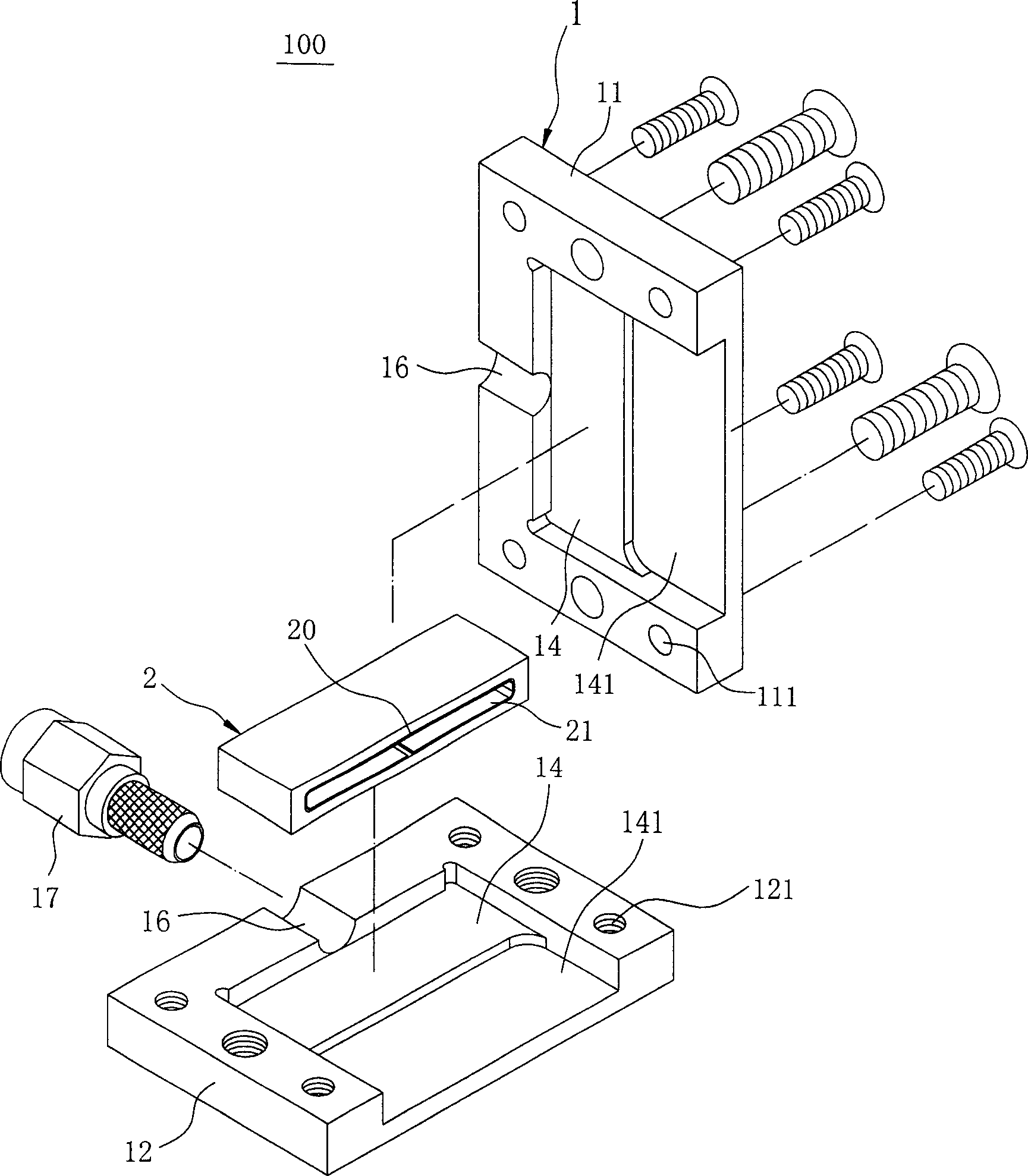
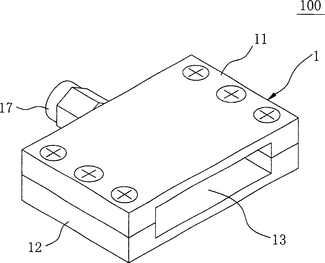
[0049] refer to Figure 1 to Figure 6 As shown, the present invention provides an antenna coupling test device, the test device 100 is used to test a device under test 300, especially the device under test 300 is a plate-shaped body, and the plate-shaped body is a built-in antenna 4 circuit board 3, thereby testing the power, field effect, etc. of the antenna 4.

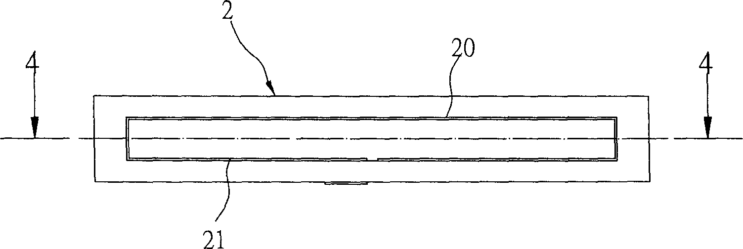
[0050] The test device 100 includes a housing 1, an insulating material 2 disposed in the housing 1 and an electrical connector 17 disposed in the housing 1. The housing 1 is made of aluminum or aluminum alloy, and has the same Since the power leakage blocking function of the isolation cover is well known, the insulating material 2 can be, for example, Bakelite or other suitable insulating materials.

[0051] This ...


PUM


Abstract

A air wire coupling test device, especially refers to the test device that used to test the air wire of the device waiting for measuring, to get the testing values such as the air wire power , effect, the device waiting for measuring is clintheriform. That test device includes: one crust that setting a slot in one side, and the slot is convenient for inserting which relative to the said device waiting for measuring; one insulating material which is set in the slot of the crust, one capacity room, and one metal sheet set in the interior wall of the capacity room; and the electronic connector set up in the other side of the crust , both the electronic connector and the said metal sheet ,the metal sheet and the said crust are linked electrically.

Description

technical field [0001] The present invention relates to an antenna coupling testing device, in particular to an antenna coupling testing device used for testing such antennas built on circuit boards. Background technique [0002] Electronic products with antennas must be tested for power and field effects before shipment. Traditionally, there are two test methods for this type of test, which are described below. [0003] The first method is to use a signal line to transmit the signal to a test instrument. This method requires an external electrical connector in order to transmit the signal to the test instrument. [0004] The second method is to place the antenna of the device under test and the antenna of the receiving signal end in an isolation cover for testing, so as to prevent power leakage and avoid interference or influence with the operation or testing of other products on the production line. [0005] In the above two methods, whether an external electrical connect...

Claims


Application Information

Patent Timeline
Patent Type & Authority Applications(China)
IPC IPC(8): G01R29/08G01R29/10G01R31/00H04B17/00H04B17/12
Inventor 周黄弘亚余秋庆
Owner Z-COM INC
Why Eureka
Try Eureka