Message speed limit method

A message and message limit technology, applied in the field of message processing, to achieve the effect of simple implementation, less resource occupation, and basically stable quantity

Active Publication Date: 2006-01-25
NEW H3C TECH CO LTD
View PDF0 Cites 35 Cited by
  • Summary
  • Abstract
  • Description
  • Claims
  • Application Information

AI Technical Summary

Problems solved by technology

[0010] The technical problem solved by the present invention is to provide a method for limiting the rate of messages. The method solves the problem that when the number of messages received by the CPU exceeds the predeterm

Method used


Image

  • Message speed limit method
  • Message speed limit method
  • Message speed limit method

Examples


Example Embodiment

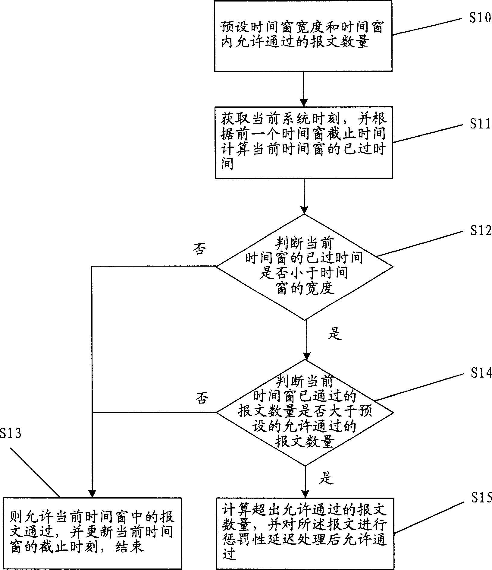
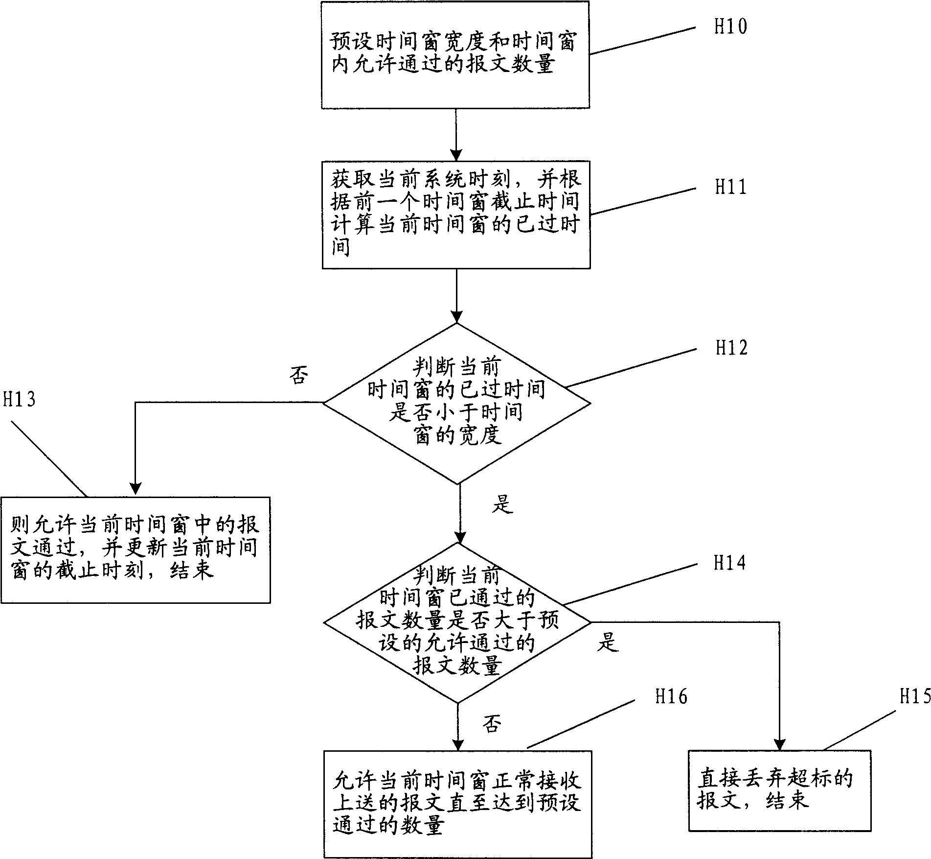
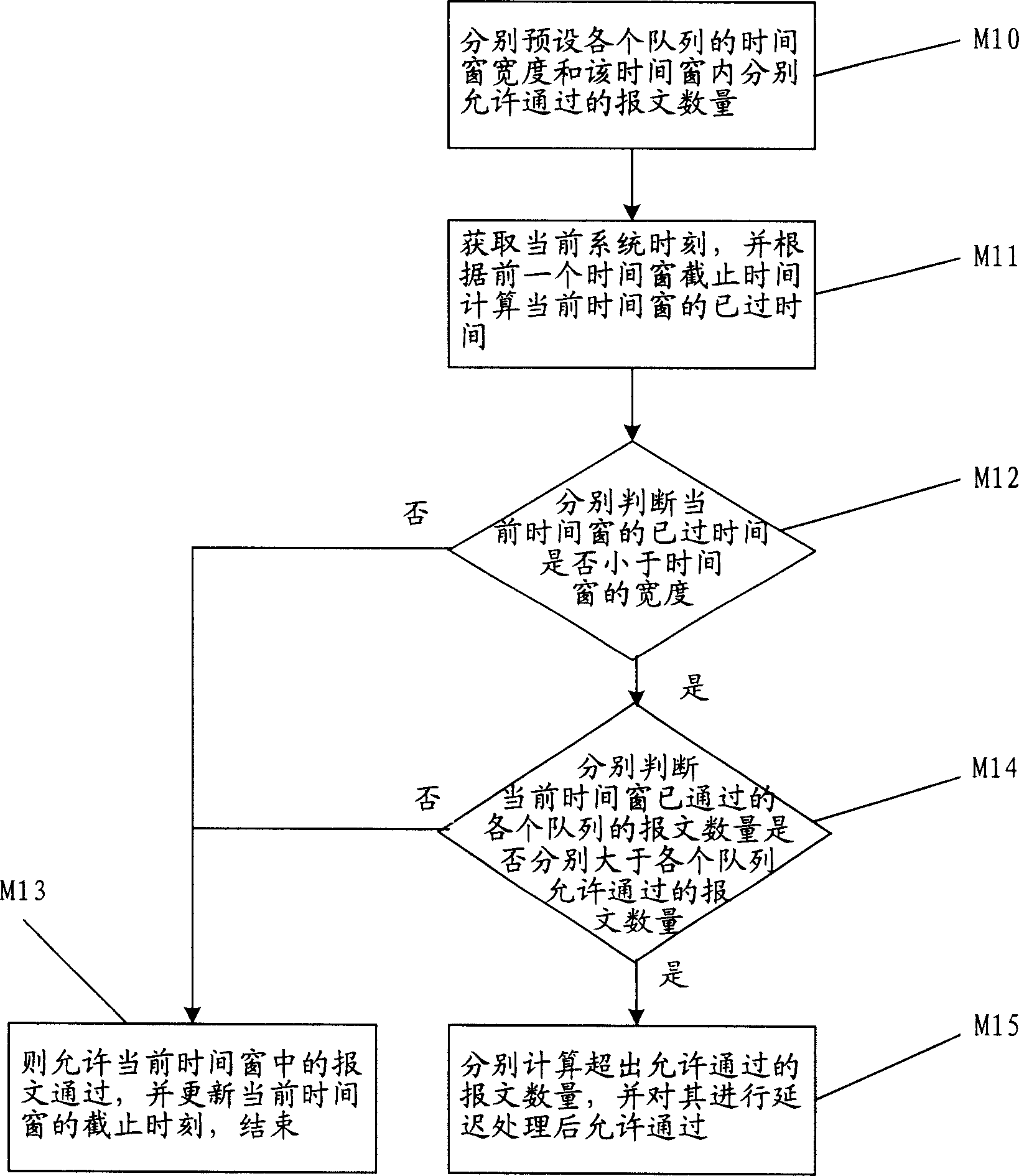
[0048] The core of the present invention is to control the flow of messages received by the CPU by setting the flow of messages within a time window, and adopt a corresponding penalty mechanism for messages that exceed the unit time window, that is, delay processing, to ensure that the flow of messages within the unit time window is delayed. The number of sent messages is basically stable, so as to achieve the purpose of optimizing the use of CPU resources and protecting the CPU when the system suffers from broadcast storms or hacker attacks.

[0049] The present invention provides a universal and simple message rate limiting method, which performs traffic rate limiting or traffic shaping on CPU messages sent by software means, and is suitable for various types of CPUs and software operating systems. The following takes the implementation on the embedded operating system Vxworks as an example to further describe the technical solution of the invention.

[0050] Please refer to fig...


PUM


Abstract

A method for limiting speed of message includes presetting width of time window and number of message to pass , obtaining current system time and calculating out passed time of current time window ( CTW ) , judging whether passed time of CTW is less that time window width or not , allowing message to pass CTW and refreshing end time of CTW if it is not , judging whether number of passed message is greater that number of message being allowed to pass or not if it is , calculating out message number exceeding to pass , making flow delay for them then allowing them to pas if it is or otherwise allowing message in CTW to pass and refreshing end time of CTW .

Description

technical field [0001] The invention relates to the technical field of message processing, in particular to a message rate limiting method. Background technique [0002] With the rapid development of communication chip technology, the processing speed of data communication equipment including routers and Ethernet switches is getting faster and faster, the port density is getting bigger and bigger, and the functions and protocol features supported are becoming more and more abundant. There are more and more protocol packets, interrupts, and messages that need to be processed by the CPU of the device. On the one hand, these protocol messages are received by the CPU, analyzed, and then placed in the message processing queue of the corresponding software protocol processing unit to wait for processing; on the other hand, the processing speed of the current CPU is getting faster and faster. Some devices also have problems such as packet processing queue overflow and memory usage...

Claims


Application Information

Patent Timeline
IPC IPC(8): H04L12/56H04L47/22
Inventor 王俊
Owner NEW H3C TECH CO LTD
Why Eureka
Try Eureka