

Image sensor unit and image reacter
An image reading device, image sensor technology, applied in the direction of image communication, electrical components, etc., to achieve the effects of suppressing the fluctuation of the combined light amount, high irradiation light amount, and suppressing the fluctuation of the reading light amount
- Summary
- Abstract
- Description
- Claims
- Application Information
AI Technical Summary
Problems solved by technology
Method used
Image

Examples
Embodiment approach 1
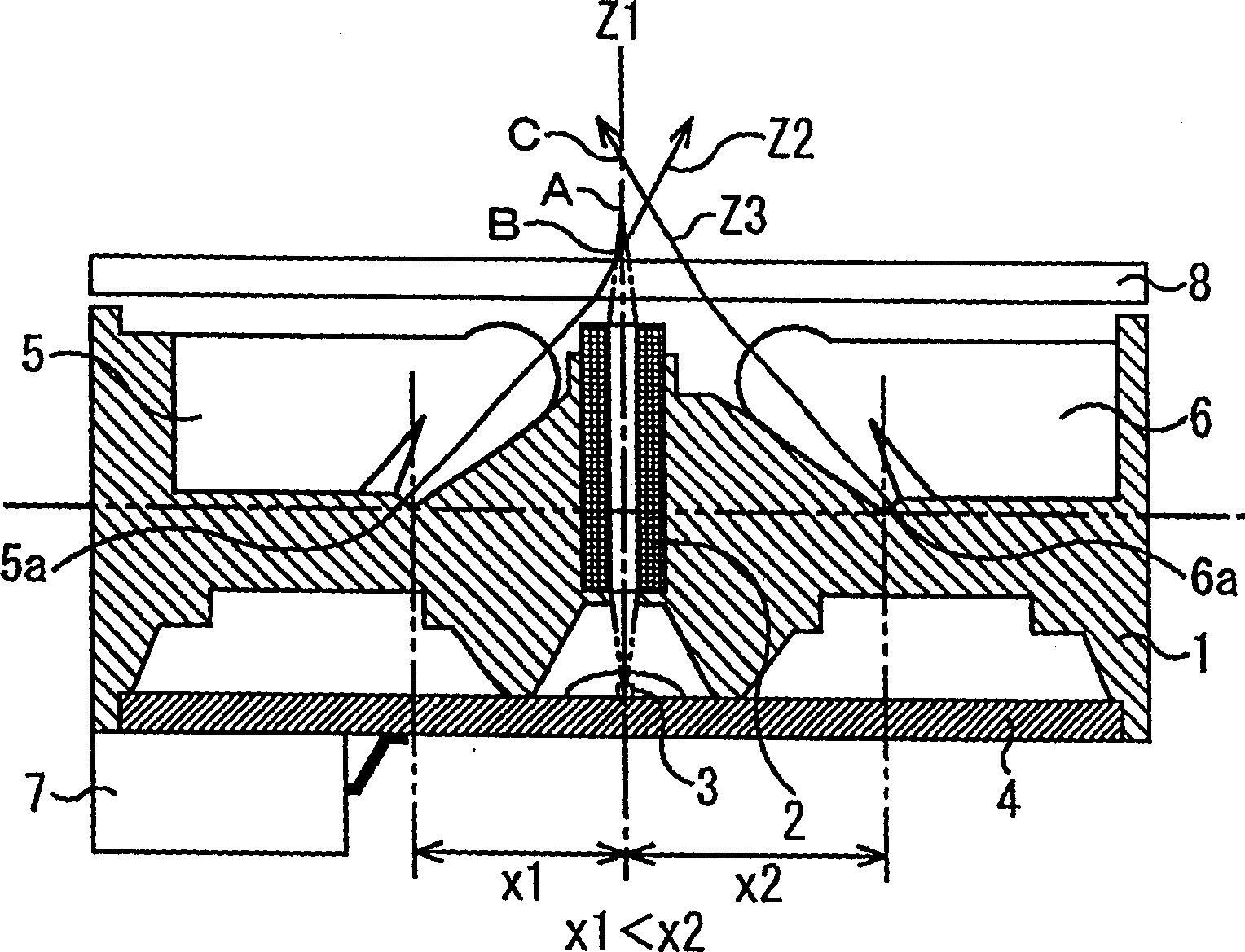
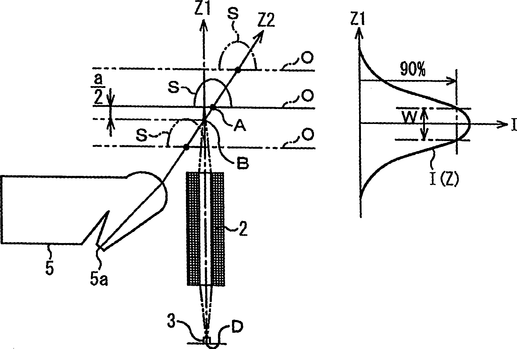
[0037] First, Embodiment 1 of the present invention will be described. figure 1It is a sectional view showing the configuration of the CIS unit according to Embodiment 1 of the present invention. In this embodiment, illuminating devices 5 and 6 for illuminating a document are supported on the frame 1 . Below the frame 1 is installed a sensor base 4 equipped with a sensor array 3. The sensor array 3 is equipped with a plurality of light receiving units that photoelectrically convert the optical image of the original into an electrical signal. The optical image of the original is also supported on the frame 1. Lens array (imaging device) 2 that images on sensor array 3 . The sensor array 3 is located at the sensor-side focal point of the lens array 2 . In addition, a terminal 7 for connecting the sensor array 3 and an external device is mounted on the lower side of the sensor chassis 4 . Furthermore, LEDs (not shown) are provided as light sources in the lighting devices 5 an...
Embodiment approach 2
[0066] Embodiment 2 of the present invention will be described below. Figure 5 It is a sectional view showing the configuration of a CIS unit according to Embodiment 2 of the present invention. Furthermore, in and figure 1 Components that are the same as in the first embodiment shown are given the same reference numerals.
[0067] In the present embodiment, the height h1 from the base point 5 a on the surface of the sensor array 3 is lower than the height h2 from the base point 6 a of the sensor array 3 . Furthermore, even in this embodiment, the illuminating device 5 is arranged so that the intersection point B of the optical axis Z2 and the optical axis Z1 is closer to the lens array 2 than the focal point A on the document side of the lens array 2, and the illuminating device 6 is arranged so that the optical axis Z3 The intersection point C with the optical axis Z1 is farther from the lens array 2 than the document-side focal point A of the lens array 2 .
[0068] Als...
Embodiment approach 3
[0071] Embodiment 3 of the present invention will be described below. Figure 6 It is a cross-sectional view showing the configuration of a CIS unit according to Embodiment 3 of the present invention. Furthermore, in and figure 1 The same reference numerals are assigned to the same components in the first embodiment shown.
[0072] In this embodiment, the distance between the optical axis Z1 and the base points 5a and 5b is the same, and the heights from the base points 5a and 5b on the surface of the sensor array 3 are also the same, and the part of the lighting device 5 supporting the frame 1 is inclined inwardly. The part of the lighting device 6 supporting the frame 1 is inclined to the outside. Therefore, compared with Embodiment 1, the lighting devices 5 and 6 are rotated clockwise, and the optical axes Z2 and Z3 of the illumination light from these lighting devices are also rotated clockwise. Therefore, the angle formed by the optical axis Z2 and the optical axis Z1...
PUM
 Abstract
Description
Claims
Application Information