

Centrifugal separator
A centrifugal separator and separator technology, which is used in centrifuges, centrifuges with rotating drums, etc., to achieve the effects of large processing gas flow, high separation efficiency, and reduced power consumption
- Summary
- Abstract
- Description
- Claims
- Application Information
AI Technical Summary
Problems solved by technology
Method used
Image

Examples
Embodiment Construction
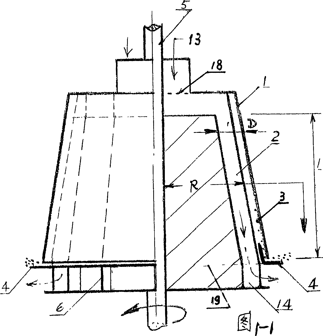
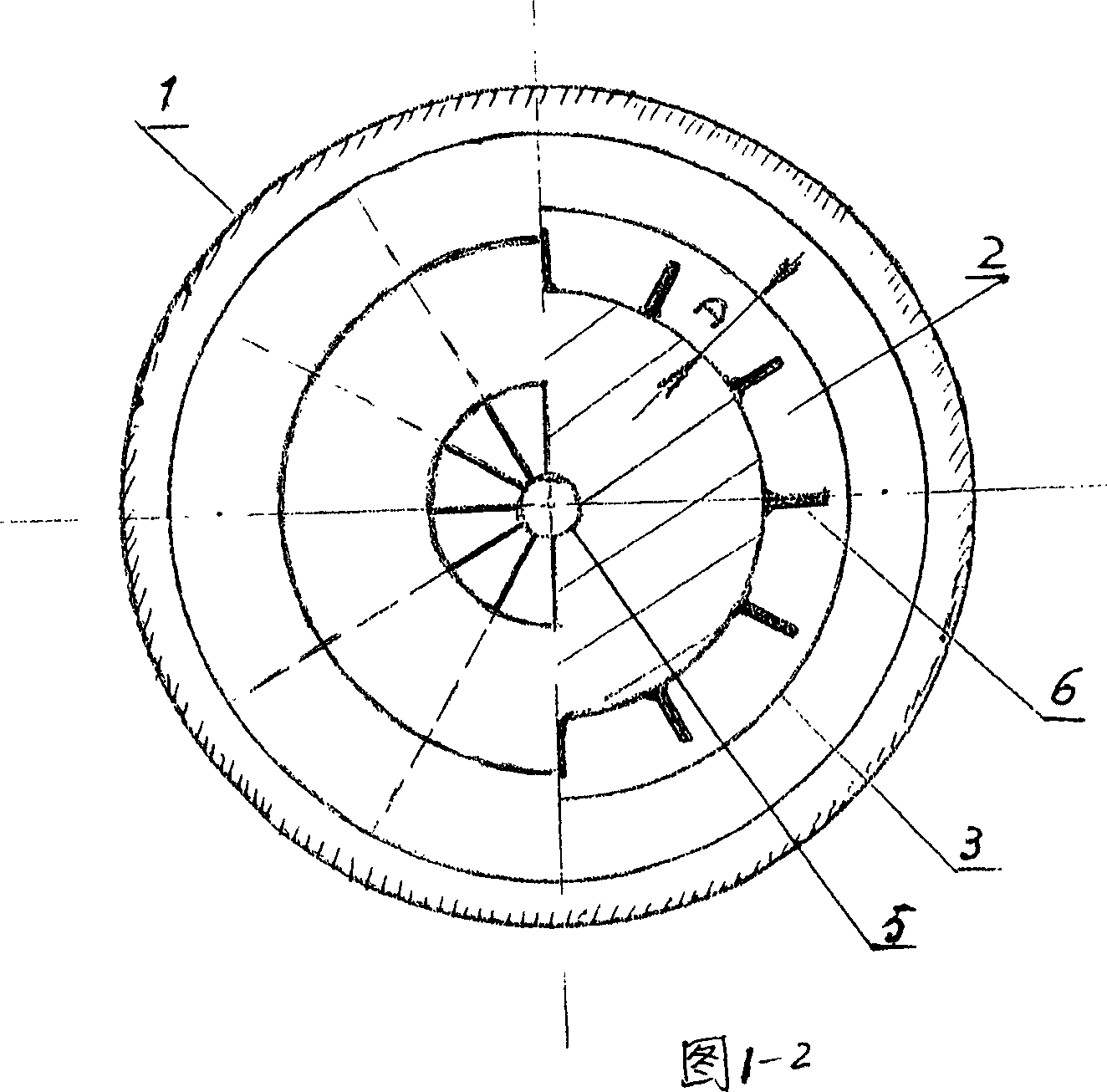
[0023] Fig. 1-1, Fig. 1-2 represent the schematic diagram of the longitudinal and transverse sectional views of the centrifugal separator settling tubes of the present invention that are used for gas dust removal. 6 It is obtained by evenly separating the space between the two inner and outer circular platform sides symmetrical to the rotation axis 5 in the circumferential direction, wherein the outer circular platform is smooth and is used as the settlement surface 3, and the separating plate 6 and The settling surfaces 3 are not connected but leave a gap, which makes the settling tubes connected, increases the area of the settling surfaces 3 and helps prevent the accumulation of dust.
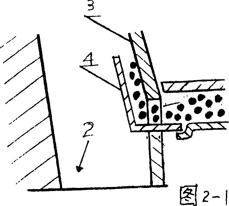
[0024] The settling surface 3 extends continuously from the inlet end face 18 perpendicular to the rotating shaft 5 at the entrance to the outlet end face 19 perpendicular to the rotating shaft 5 at the outlet. The length of the settling tube 2 in the axial direction is L, and its average wi...
PUM
 Abstract
Description
Claims
Application Information