Anti-splashing device and method used for welding sensor

An anti-spatter and sensor technology, used in auxiliary devices, welding equipment, auxiliary welding equipment, etc., can solve the problems of affecting the welding seam detection accuracy, time-consuming, difficult to clean, etc. Small footprint effect

Pending Publication Date: 2021-04-13
XIAN ZHONGKE PHOTOELECTRIC PRECISION ENG CO LTD
View PDF1 Cites 2 Cited by
  • Summary
  • Abstract
  • Description
  • Claims
  • Application Information

AI Technical Summary

Problems solved by technology

However, a large amount of welding slag splash and dust will be generated during the welding process. Long-term welding will cause a large amount of welding slag particles to adhere to the surface of the unprotected front light window protection lens of the sensor and it is difficult to clean up, which will affect the accuracy of weld detection and require frequent manual replacement. The light window protects the lens to ensure the normal operation of the sensor, which is labor-intensive and expensive
[0003] CN 109702395 A discloses an anti-splash component form of a pneumatic component that executes flipping of the baffle. This structural form requires a large space for flipping the baffle, and when the laser sensor is close to the welding torch, collisions between the baffle and the welding torch are prone to occur, and the baffle Hidden danger of collision with welding workpiece
After long-term welding use, a large number of welding slag particles will stick to the baffle, which needs to be cleaned manually

Method used


Image

  • Anti-splashing device and method used for welding sensor
  • Anti-splashing device and method used for welding sensor
  • Anti-splashing device and method used for welding sensor

Examples


Embodiment Construction

[0029] The present invention will be described in detail below in conjunction with the accompanying drawings and specific embodiments, where the schematic embodiments and descriptions of the present invention are used to explain the present invention, but not to limit the present invention.

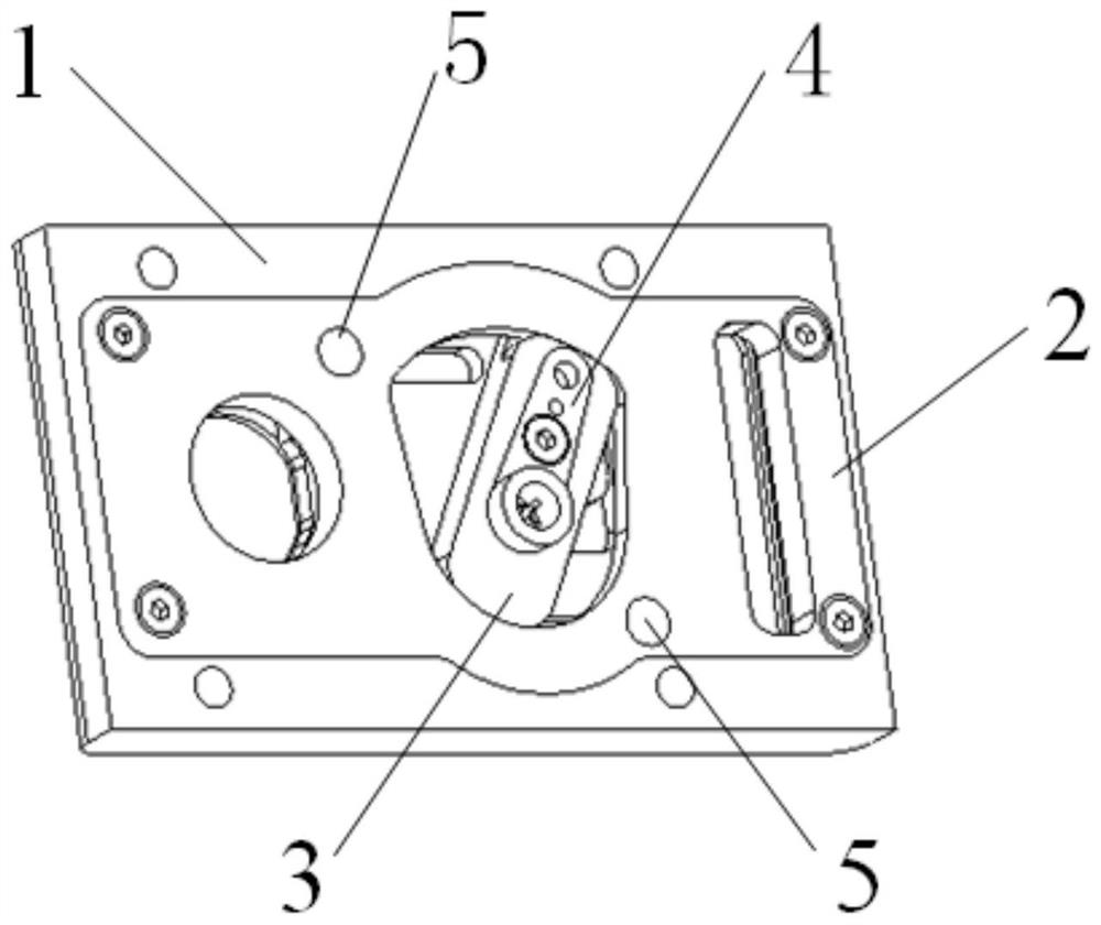
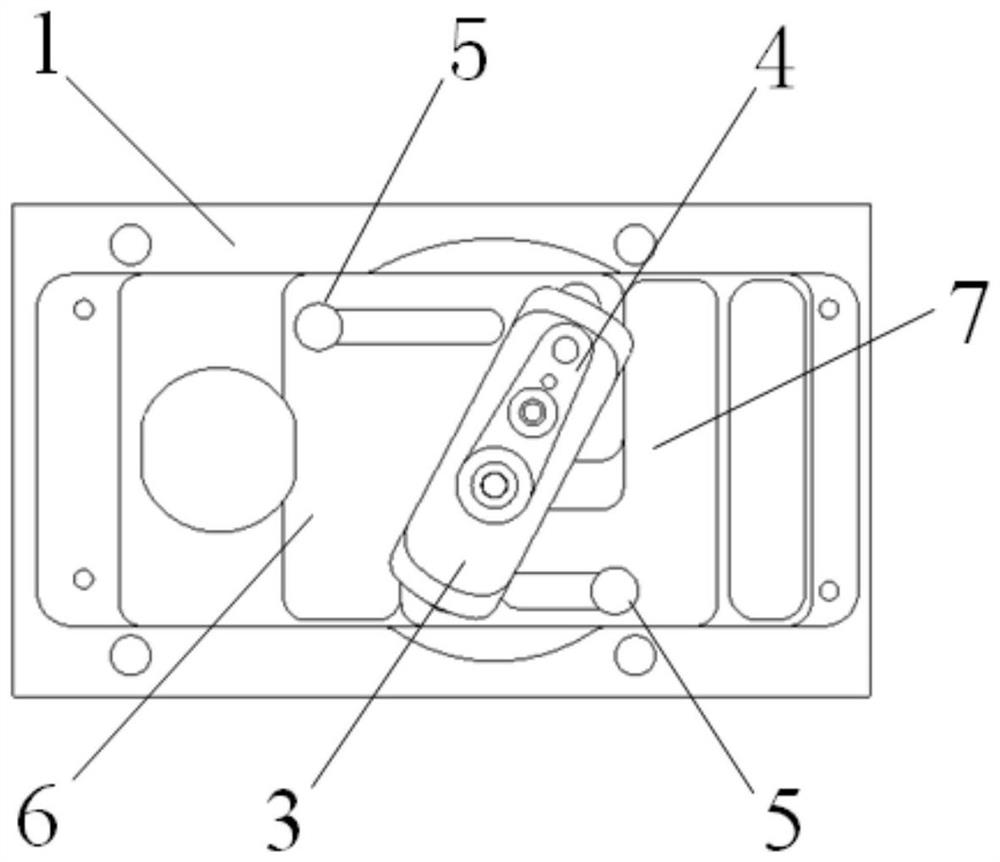
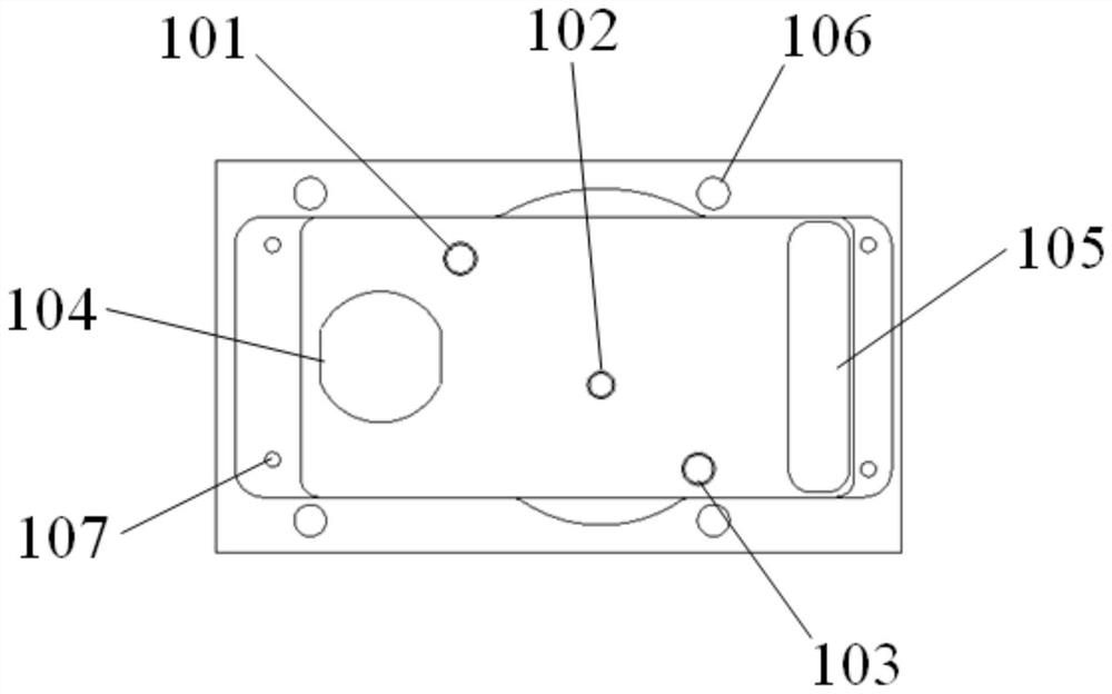
[0030] Such as figure 1 , figure 2 As shown, an anti-splash device for welding sensors provided by the embodiment of the present invention includes a base 1, a cover plate 2, a handle 3, a swing rod 4, a pin 5, a lens block 6 and a laser block 7; The base 1 is provided with a first lens light exit hole 104 and a first laser light exit hole 105; inside the first lens light exit hole 104 and the first laser light exit hole 105, the base 1 is provided with a lens stopper 6 and a laser stopper 7 , a rocking handle 3 and a swing rod 4 are arranged between the lens block 6 and the laser block 7; the swing rod 4 meshes with the output shaft gear of the steering gear, drives the rocker 3 to rot...


PUM


Abstract

The invention discloses an anti-splashing device and method used for a welding sensor. The anti-splashing device comprises a base, and a lens light outlet hole and a laser device light outlet hole are formed in the base. A lens blocking piece and a laser device blocking piece are arranged at the positions, on the inner sides of the lens light outlet hole and the laser device light outlet hole, of the base, and a rocking handle and a swing rod are arranged between the lens blocking piece and the laser device blocking piece. The swing rod is engaged with a steering engine output shaft gear, drives the rocking handle to rotate and converts motion into reciprocating linear motion of the lens blocking piece and the laser device blocking piece in the base, and therefore opening and closing of the lens light outlet hole and the laser device light outlet hole are achieved. The device has the advantages of being compact in structure, small in occupied space and capable of achieving self-cleaning. In the using process of a laser welding seam sensor, the influence of splashed welding slag particles on the welding sensor can be effectively blocked. The structure can be applied to a line structured light laser sensor, a surface structured light laser sensor, a binocular sensor and other occasions needing lens protection.

Description

technical field [0001] The invention belongs to the technical field of laser seam sensors for robots, and in particular relates to an anti-splash device and method for laser seam sensors for robot welding torches. Background technique [0002] In the field of welding robots, the laser seam sensor, as an important part, has the function of seam identification and detection, obtains the position information of the seam, and transmits it to the robot to guide the robot to perform accurate welding. However, a large amount of welding slag splash and dust will be generated during the welding process. Long-term welding will cause a large amount of welding slag particles to adhere to the surface of the unprotected front light window protection lens of the sensor and it is difficult to clean up, which will affect the accuracy of weld detection and require frequent manual replacement. The light window protects the lens to ensure the normal operation of the sensor, which is time-consum...

Claims


Application Information

Patent Timeline
Patent Type & Authority Applications(China)
IPC IPC(8): B23K37/00
CPCB23K37/00
Inventor 张保军吴易明李柏杨靳亚丽董林佳
Owner XIAN ZHONGKE PHOTOELECTRIC PRECISION ENG CO LTD
Why Eureka
Try Eureka