Centrifugal separator

A centrifugal separator and separator technology, applied in centrifuges, centrifuges with rotating drums, etc., to achieve the effects of large gas flow rate, high separation efficiency, and reduced power consumption

Inactive Publication Date: 2008-01-09
潘雨力
View PDF7 Cites 0 Cited by
  • Summary
  • Abstract
  • Description
  • Claims
  • Application Information

AI Technical Summary

Problems solved by technology

[0003] The technical problem to be solved by the present invention is to solve the problems of low separation efficiency, complex structure and high power consumption of the existing inertial centrifugal dust removal device. The purpose of the present invention is to provide an effective centrifugal separator to overcome The above defects in the prior art, the present invention relies on the following technical solutions to achieve, a centrifugal separator, including a central rotating shaft and an outer casing, the centrifugal separator outer casing is provided with a rotationally symmetrical arrangement with respect to the central rotating shaft and A settling tube that can rotate synchronously around the axis of rotation. The settling tube is a flat plate called a partition plate that evenly divides the space between the sides of the inner and outer round tables that are symmetrical to the rotation axis. The settling tube surrounds The rotating shaft is arranged in the shape of a conical shell and arranged along the side of the busbar. The wall surface of the settling tube on the far side from the rotating shaft is a smooth settling surface. The settling surface is a smooth curved surface or a plane. The radius of rotation on the upper pair of axes of rotation is greater than the radius of rotation on the inlet face

Method used


Image

  • Centrifugal separator
  • Centrifugal separator
  • Centrifugal separator

Examples


Embodiment Construction

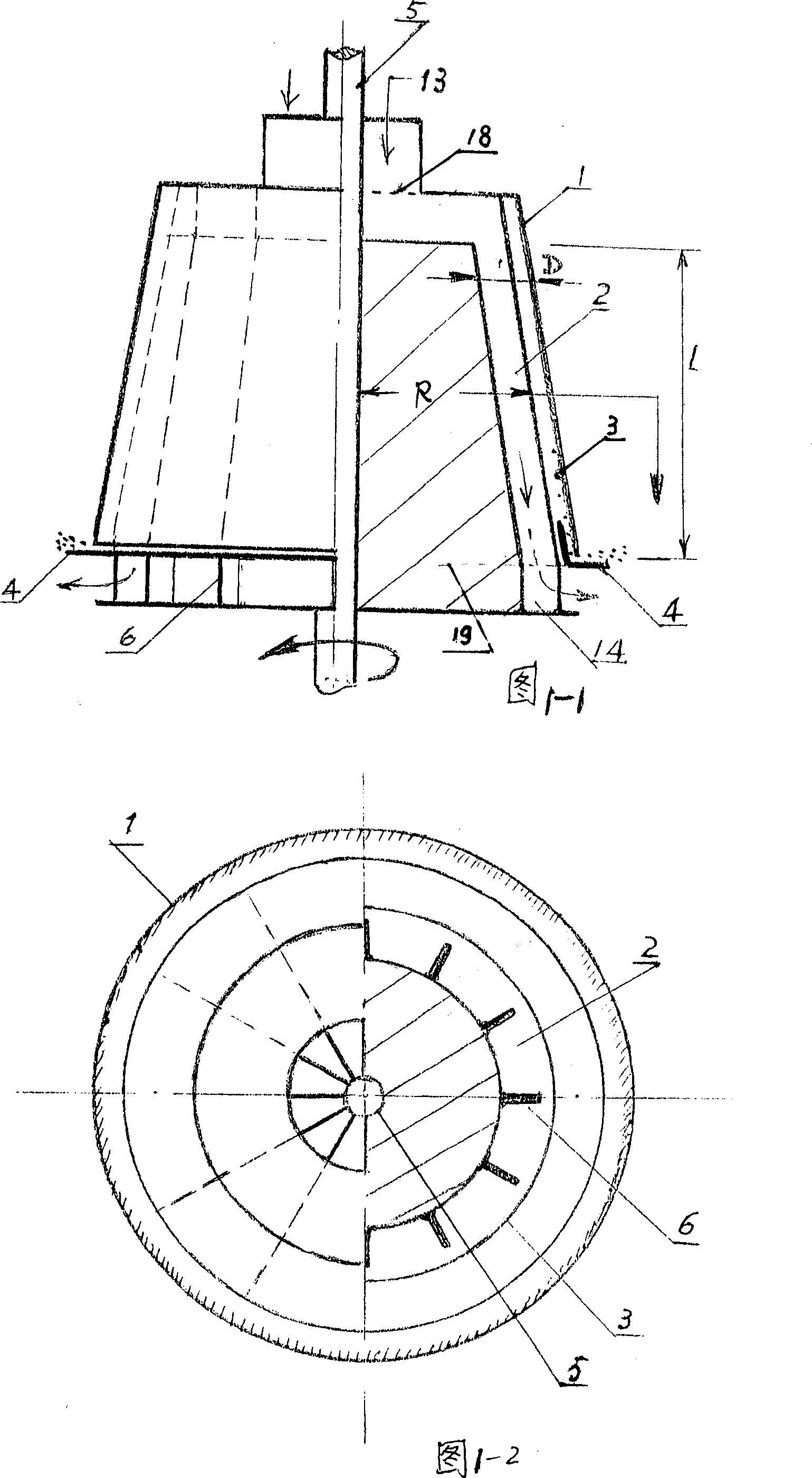
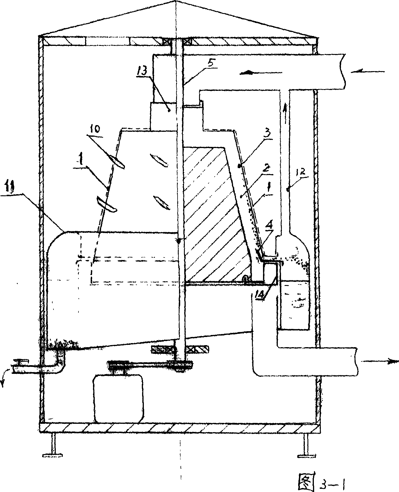
[0024] Fig. 1-1 and Fig. 1-2 show that the present invention is used for centrifugal separation of gas dust removal

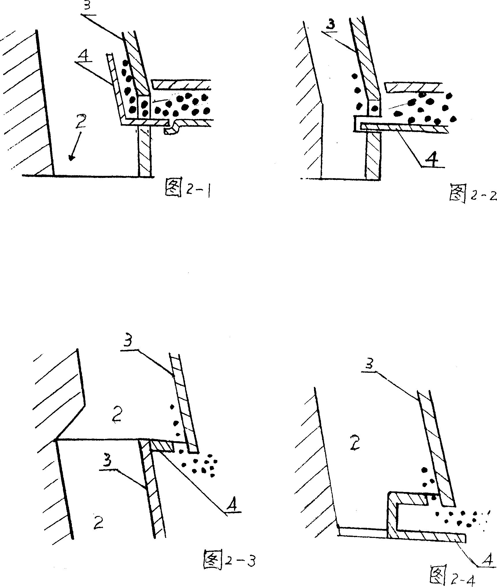
[0025] The principle schematic diagram of the longitudinal and transverse cross-sectional views of the settling tubes of the device interpenetrating with each other. In the figure, the outer casing 1 contains the settling tube 2 inside and is evenly separated by the partition plate 6 in the circumferential direction. Two inner and outer circular platforms symmetrical to the rotating shaft 5 The space sandwiched by the sides is obtained, wherein the outer round table surface is smooth, which is used as the settlement surface 3, and there is no connection between the partition plate 6 and the settlement surface 3 but a gap, which makes each settlement The connection between the pipes increases the area of ​​the settling surface 3 and helps to prevent the accumulation of accumulated dust.

[0026] The settling surface 3 extends continuously from the inlet end face...


PUM


Abstract

A centrifugal separator for treating polluted gas is composed of a central rotary shaft, an external casing, and several settling tubes, which are arranged in axial symmertrical mode relative to central rotary shaft to form a circular table shape and along the mother lines to become inclinded, and are revolving around said central rotary shaft. Said settling tube has a smooth settling inner surface at its far end. Its advantages are high separation efficiency and gas flow, and self-cleaning.

Description

technical field [0001] The invention belongs to the field of industrial environmental protection machinery and equipment, in particular to a centrifugal separator utilizing inertial centrifugal force in industrial production. Background technique [0002] In the prior art, the principle of the separator that uses centrifugal force to remove dust is mainly: use the rotating blades to rotate the dusty gas at high speed, and the dusty gas leaves the blades to form a high-speed whirlwind, and then use the centrifugal force generated by the rotation in a small space The dust particles are settled in a fixed dust-containing structure. There are several problems in this device: first, the velocity of the gas in the space from its center to the fixed settlement wall changes from a large to 0, and the sudden change of the velocity gradient reduces the separation effect; Furthermore, after the dust particles are deposited on the fixed settling wall, the centrifugal force suddenly decr...

Claims


Application Information

Patent Timeline
Patent Type & Authority Patents(China)
IPC IPC(8): B04B1/08B04B1/10B04B7/08B04B15/02B04B15/00
Inventor 潘雨力
Owner 潘雨力
Why Eureka
Try Eureka