Die in use for molding component of concrete filled double thin wall

A technology of hollow thin-walled and forming moulds, which is applied in the direction of moulds, building components, reinforced molding, etc., and can solve the problems of easy breakage of open thin-walled tubes or thin-walled boxes, and inconvenient demoulding.

Inactive Publication Date: 2006-02-01
邱则有
View PDF3 Cites 19 Cited by
  • Summary
  • Abstract
  • Description
  • Claims
  • Application Information

AI Technical Summary

Problems solved by technology

Such as the female mold, as can be seen from their drawings, it includes a side mold surface and a bottom mold surface, and the side mold surface and the bottom mold surface form a female mold. This kind of female mold is the female mold of the o

Method used


Image

  • Die in use for molding component of concrete filled double thin wall
  • Die in use for molding component of concrete filled double thin wall
  • Die in use for molding component of concrete filled double thin wall

Examples


Embodiment Construction

[0067] The present invention will be further described below in conjunction with the accompanying drawings and embodiments.

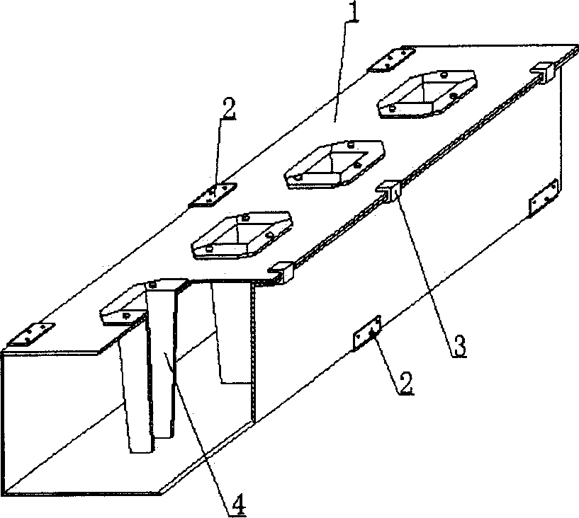
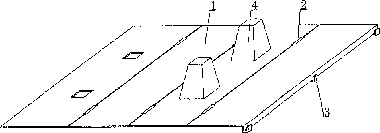
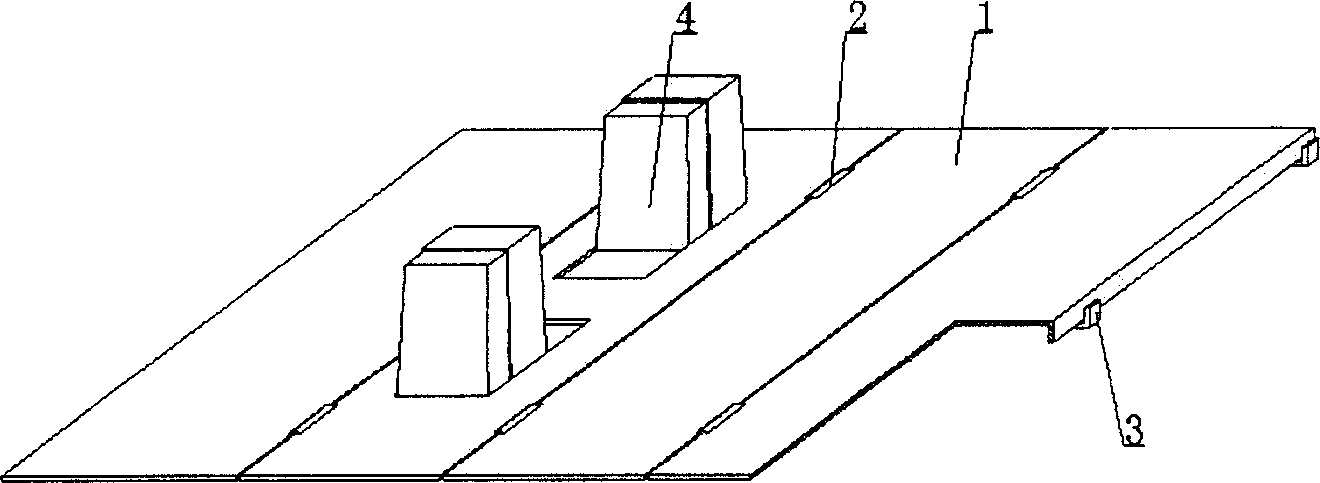
[0068] As shown in the accompanying drawings, the present invention includes a template 1, a rotatable part 2, and a fastening part 3. The template 1 is connected by the rotatable part 2, and the connected template 1 can rotate relatively. After the template 1 is closed, it is fixed by the fastening part 3. It is characterized in that at least three templates 1 are connected side by side in sequence, and at least one fixed or movable core mold 4 protruding from the mold surface of the template 1 is arranged on at least one template 1 . figure 1 It is a structural schematic diagram of Embodiment 1 of the present invention. In each accompanying drawing, 1 is a template, 2 is a rotatable part, 3 is a fastening part, and 4 is a mandrel. In the following accompanying drawings, those with the same number have the same description. Such as figure 1 As shown,...


PUM


Abstract

A mould for forming the thin-wall hollow concrete member is composed of the form boards, the turnable parts for connecting the form boards in turnable mode, and the fasteners for fastening the closed form boards. It features that at least 3 form boards are sequentially connected and at least one form board has the fixed or movable male core mould to generate hole or pit on the product. Its advantages are simple structure and high strength.

Description

(1) Technical field [0001] The invention relates to a molding die for a concrete-filled hollow thin-walled component. (2) Background technology [0002] At present, cast-in-place reinforced concrete hollow slabs, especially the non-core-pulling hole-forming process of cast-in-situ reinforced concrete hollow slabs, are generally filled with thin-walled tubes or thin-walled boxes, which can meet the needs of various hollow slabs for evacuating concrete. For example, the publication number applied by the applicant on May 29, 2002 is CN1462680A, and the title is "Hollow Tube Forming Tool", which is characterized in that it includes two interface edges, a stretchable elastic cylinder, a brace, a tightening piece, an interface The side is fixed on the wall edge of the tension-type elastic cylinder along the length direction, the supporting part is wrapped in the end of the tension-type elastic cylinder, and the tightening part is locked on the edge of the interface or hugged tight...

Claims


Application Information

Patent Timeline
IPC IPC(8): B28B21/82B28B21/56B28B7/04B28B7/16B28B7/26B28B7/28E04B5/16
Inventor 邱则有
Owner 邱则有
Why Eureka
Try Eureka