Circular corridor for spinning of urethane elastic fiber

A spinning shaft and spandex technology, which is applied in the field of spinning shafts and circular spandex spinning shafts, can solve the problems of yarn bundle cross-section, turbulent hot air flow, large temperature difference, etc. performance, improve production efficiency, and avoid the effect of being blown flat

Active Publication Date: 2006-02-01
JIANGYIN L V CHEM FIBER PROCESS TECH
View PDF0 Cites 17 Cited by
  • Summary
  • Abstract
  • Description
  • Claims
  • Application Information

AI Technical Summary

Problems solved by technology

Before the present invention was made, in the spandex spinning process, the square tunnel was usually used for side blowing, and the air flow was perpendicular to the traveling direction of the tow during work, and the processing consistency of the rectification device was poor. The cross-section deformation of the tow affects the whole spinning forming process
At the same time, the heat tracing system is partially heat traced, the temperature difference is large, and the solvent volatilizes unevenly in the tunnel, which directly affects the product quality of spandex yarn

Method used


Image

  • Circular corridor for spinning of urethane elastic fiber
  • Circular corridor for spinning of urethane elastic fiber
  • Circular corridor for spinning of urethane elastic fiber

Examples


Embodiment Construction

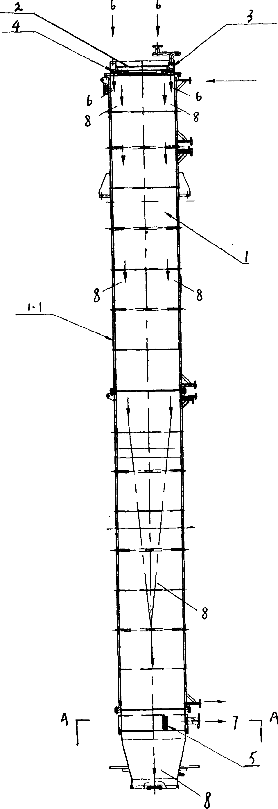
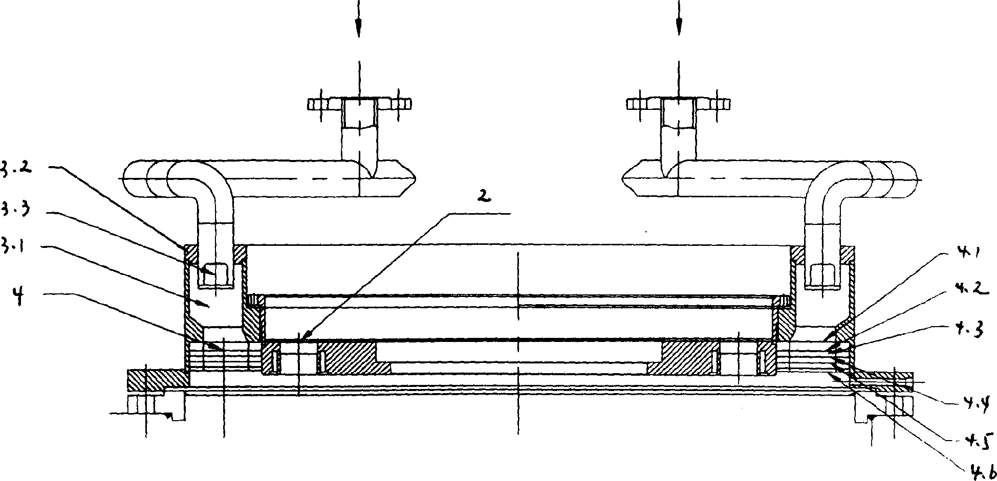
[0011] see Figure 1~2 , The invention is a circular spandex spinning tunnel. It is mainly composed of cylindrical tunnel body 1, spinneret assembly 2, annular blower 3, annular air inlet rectifier 4, annular return air rectifier 5, hot air inlet 6 and hot air outlet 7, etc. The spinneret assembly 2 is arranged in the middle of the top of the cylindrical tunnel body 1, the annular blower 3 is arranged on the periphery of the spinneret assembly 2 at the top of the cylindrical tunnel body 1, and the annular air inlet rectifier 4 is placed under the annular blower 3 , the annular return air rectifier 5 is arranged at the bottom of the cylindrical shaft body 1, the hot air inlet 6 is arranged at the top of the annular blower 3, and the hot air outlet 7 is arranged outside the annular return air rectifier 5. The outer wall of the cylindrical tunnel body 1 is covered with a heat tracing spacer 1.1 as a whole. 8 is spandex thread among the figure.

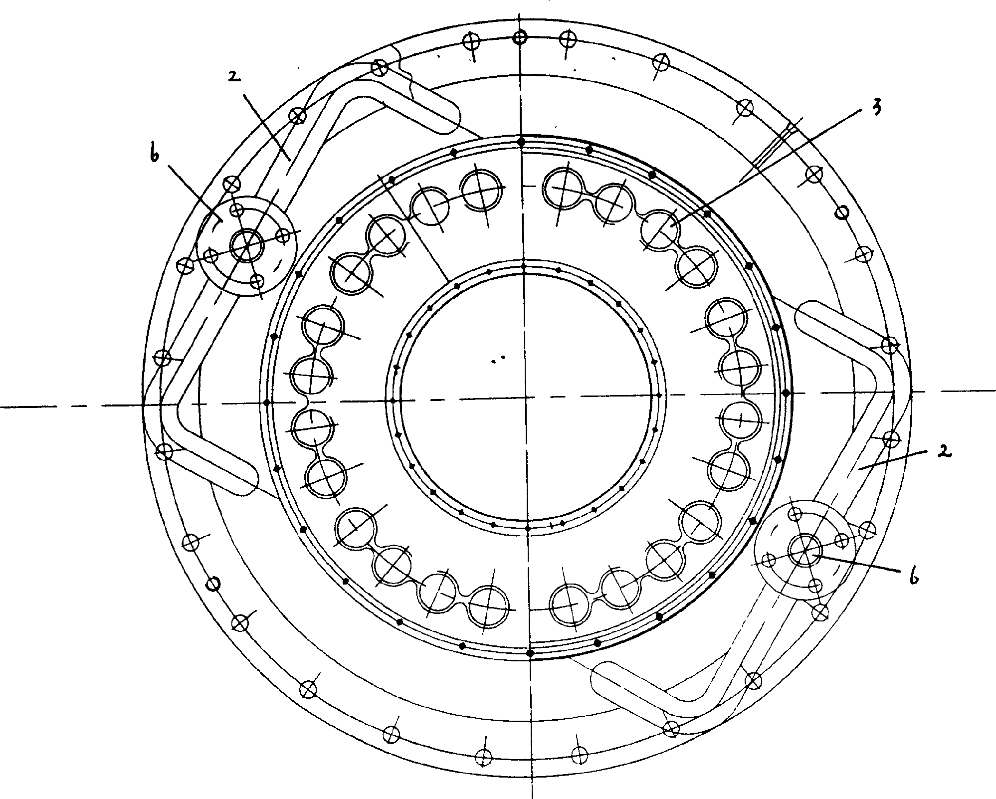
[0012] see image 3 , the annu...


PUM


Abstract

A circular channel for spinning polyurethane fibers is composed of cylindrical channel, spinneret plate module, annular air blower, annular air inlet flow-regulator, annular air-returning flow-regulator, hot airflow inlet and hot airflow outlet. Its advantages are high airflow stability, distribution uniformity and spinning quality.

Description

Technical field: [0001] The invention relates to a spinning tunnel, in particular to a circular spandex spinning tunnel. It belongs to the field of textile equipment accessories. Background technique: [0002] The spandex spinning tunnel is mainly used in the air distribution inside the spandex spinning equipment, the arrangement of the spandex tow and the heat tracing system. Before the present invention was made, in the spandex spinning process, the square tunnel was usually used for side blowing, and the air flow was perpendicular to the traveling direction of the tow during work. The cross-section of the tow is deformed, which affects the entire spinning and forming process. At the same time, the heating system traces the heat locally, the temperature difference is large, and the solvent volatilizes unevenly in the tunnel, which directly affects the product quality of the spandex yarn. Invention content: [0003] The object of the present invention is to overcome th...

Claims


Application Information

Patent Timeline
Patent Type & Authority Applications(China)
IPC IPC(8): D01D5/084D01F6/70
Inventor 李新立朱志平
Owner JIANGYIN L V CHEM FIBER PROCESS TECH
Why Eureka
Try Eureka