Apparatus and method for forming weld joints having compressive residual stress patterns

A residual compressive stress, welding joint technology, applied in welding/welding/cutting items, welding equipment, welding equipment, etc., can solve problems such as difficulty in preventing local undercuts, prolonging processing time, and thinning welding joints

Inactive Publication Date: 2006-02-01
THE BOEING CO +1
View PDF4 Cites 16 Cited by
  • Summary
  • Abstract
  • Description
  • Claims
  • Application Information

AI Technical Summary

Problems solved by technology

However, post-weld machining thins the welded joint and requires more labor-intensive and time-consuming secondary machining operations, which increases the cost and processing time of the finished component
In addition, due to the difference in hardness of the material near the weld joint caused by the reflow affected zone, it is difficult to prevent localized undercutting when performing post-weld machining that leads to fatigue initiation sites
[0013] It should now be appreciated that, until now, in addition to the above recognized problems, all post-weld processes have required secondary operations which typically add labor and / or material costs and production time to the finished assembly

Method used


Image

  • Apparatus and method for forming weld joints having compressive residual stress patterns
  • Apparatus and method for forming weld joints having compressive residual stress patterns
  • Apparatus and method for forming weld joints having compressive residual stress patterns

Examples


Embodiment Construction

[0028] The present inventions are described more fully hereinafter with reference to the accompanying drawings, in which some, but not all embodiments of the inventions are shown. The invention may be embodied in many different forms, and the invention should not be limited to these embodiments; rather, these embodiments are given so that this invention will be fully and completely disclosed, and those skilled in the art will full appreciation of the scope of the present invention. Throughout the description, the same reference numerals denote the same elements.

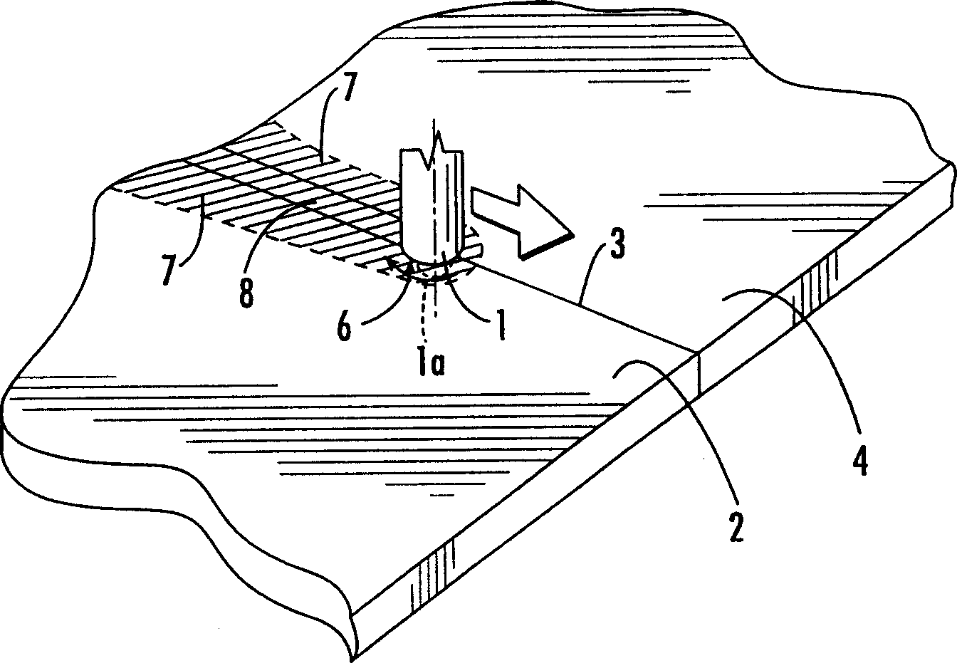
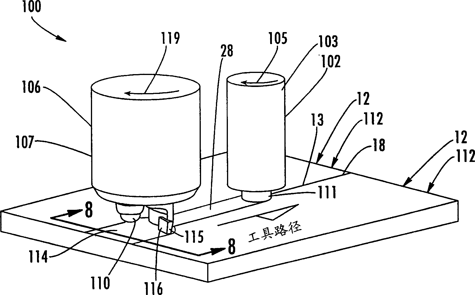
[0029] With reference to the accompanying drawings, and in particular to the Figure 8 , which shows a structural assembly 112 according to a first embodiment of the present invention. Structural assembly 112 may be used in a variety of applications including, but not limited to, vehicles, aerospace vehicles, architectural applications, marine applications, and the like. Structural assembly 112 includes one or mor...


PUM

PropertyMeasurementUnit
sizeaaaaaaaaaa

Abstract

The welding apparatus and associated method are provided. The welding apparatus includes a welding tool for forming a weld joint along the surface of at least one workpiece. The welding apparatus also includes a compression tool for selectively inducing a layer of residual compressive stress in at least a portion of the surface of the weld joint and the surface of the at least one workpiece to thereby improve the material properties of the workpiece, including corrosion resistance and fatigue strength.

Description

technical field [0001] The present invention relates to an apparatus and method for forming welded joints with improved material properties, and in particular the present invention relates to a method for forming welded joints which induces a residual compressive stress distribution pattern thereby improving the welded joint material properties. Background technique [0002] In the manufacture and construction of many types of structures, welding, such as gas welding, arc welding, resistance welding, thermal flux welding, laser welding, electron beam welding, has reduced or replaced the use of various fastening methods, which Such as bolt connection, rivet connection, etc. Such welding techniques involve complete melting of the material adjacent to the welded joint, thereby forming a liquid state, which is subsequently solidified to produce altered microstructure and properties, or solid state welding processes, which also produce highly altered metallographic states. The ...

Claims


Application Information

Patent Timeline
Patent Type & Authority Applications(China)
IPC IPC(8): B23K31/02B23K37/08B23K20/12B24B39/00C21D7/08B23K31/00B23K37/00
CPCB23K20/1275B23K2203/14C21D7/08B24B39/00B23K2203/18B23K31/02B23K2203/12B23K20/123B23K37/08B23K20/122B23K2203/10B23K2103/10B23K2103/12B23K2103/14B23K2103/18Y10T428/12493
Inventor 迈克尔·罗斯顿·詹姆士默里·W·马哈里道格拉斯·J·瓦尔登保罗·S·普雷维三世
Owner THE BOEING CO
Why Eureka
Try Eureka