Non-stick earth pack roller

A technology for pressing rollers and soil, which is applied in the field of pressing rollers, which can solve the problems of the pressing rollers sticking to the soil, uneven soil compactness, and high energy consumption of traction machinery, and achieve uniform soil compactness, solve the problem of sticking soil, and smooth the soil surface

Inactive Publication Date: 2006-02-08
JILIN UNIV
View PDF0 Cites 2 Cited by
  • Summary
  • Abstract
  • Description
  • Claims
  • Application Information

AI Technical Summary

Problems solved by technology

[0003] The purpose of the present invention is to overcome the shortcomings of sticky soil, uneven soil compactness after compaction and high energy consumption of traction machinery in the commonly used pressure rollers, and provide a non-stick soil pressure roller
[0005] The pressing roller of the present invention can effectively solve the problem of the pressing roller sticking to the soil without increasing the cost, and the compactness of the soil after pressing is uniform and the soil surface is smooth

Method used


Image

  • Non-stick earth pack roller
  • Non-stick earth pack roller
  • Non-stick earth pack roller

Examples


Embodiment 1

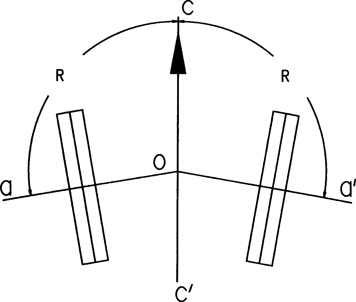
[0012] refer to figure 1 , 2 , a kind of non-clay soil pressing roll, is made of a roll frame and 2 or 4 rollers symmetrically arranged on both sides of the longitudinal axis c-c' of the roll frame. c-c' forms an included angle R of 91-99 degrees along the traveling direction of the pressure roller.

[0013] In order to realize the adjustable angle between the roller axis and the longitudinal axis of the roll stand, the rollers can be arranged on the roll stand in the manner shown in Figures 7 and 8. In the figure, 1 and 6 are pressing rollers, 2 and 5 are swing arms, and 3 Be a roller frame, 4 is a leading screw pair, 7 is a fork support, and 8 is a roller shaft. The roller frame 3 is provided with a lead screw pair 4 and a swing arm 2, 5 device for adjusting the angle of the roller axis. Rotating the screw nut can make the lead screw move axially and drive the swing arm to rotate, thereby changing the angle of the roller axis.

Embodiment 2

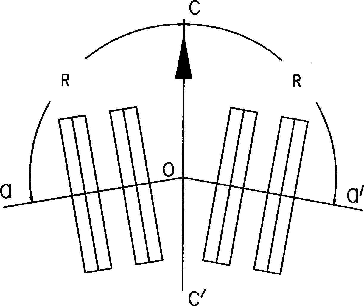
[0015] refer to image 3 , 4 , 5, a kind of non-sticky soil pressure roll, is made of a roll frame and 2 or 4 or 6 rollers symmetrically arranged on both sides of the longitudinal axis c-c' of the roll frame, the axes o-a, o-a' of the rollers An included angle R of 81-89 degrees is formed with the longitudinal axis c-c' of the roll stand along the traveling direction of the pressure roll.

Embodiment 3

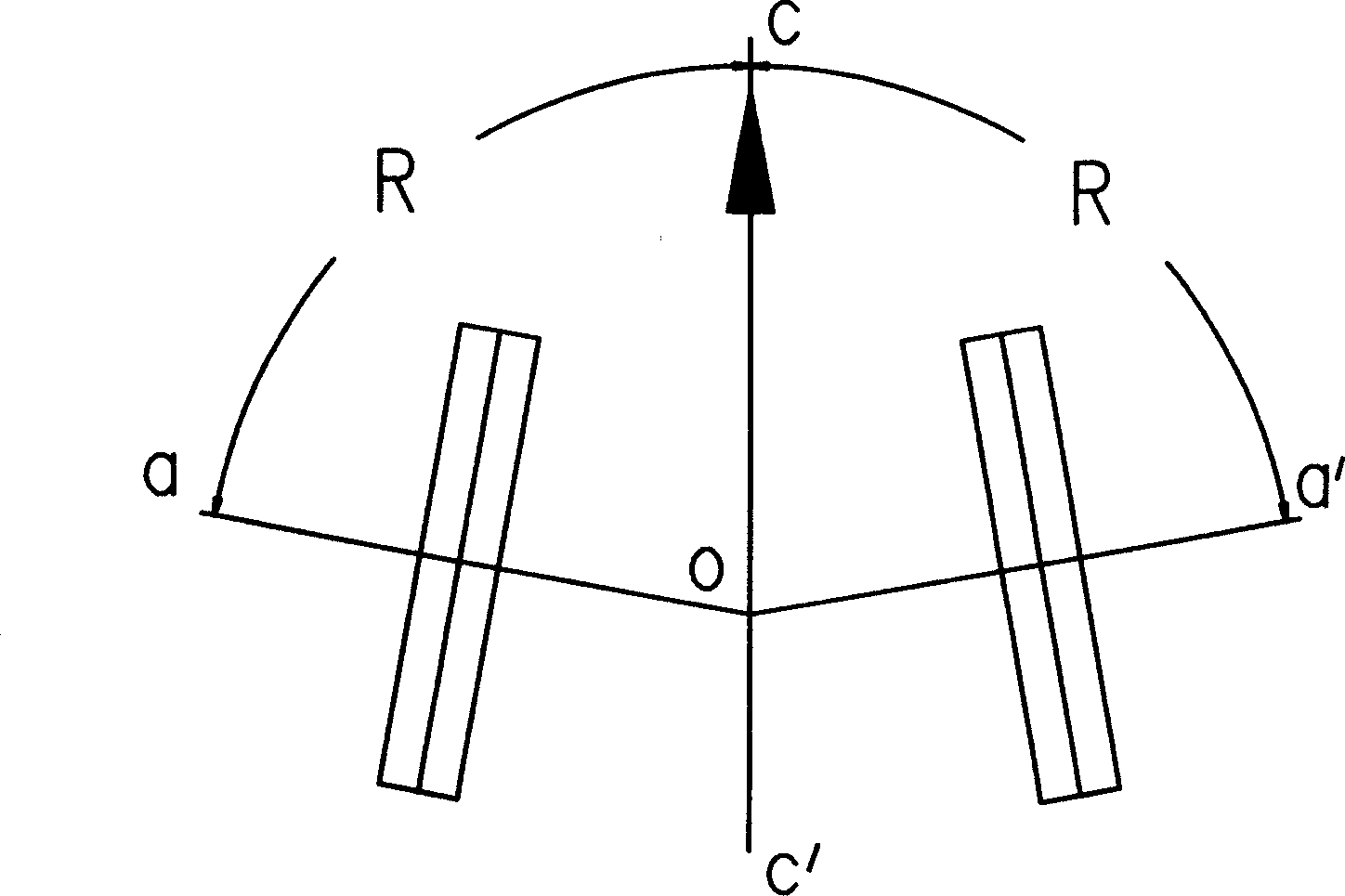
[0017] refer to Figure 6 , a non-clay soil suppression roller, which is composed of a roller frame and 4 rollers symmetrically arranged on both sides of the longitudinal axis c-c′ of the roller frame. The longitudinal axis c-c' forms an included angle R of 81-89 degrees along the direction of travel of the pressure roller; the axes o'-b, o'-b' of the other pair of symmetrical rollers G1 and G4 and the longitudinal axis c-c' of the roller frame are along the direction of the pressure roller The direction of travel forms an included angle R' of 91-99 degrees.

[0018] The pressing roller of the present invention has the characteristics of low cost, uniform soil compactness and smooth surface after pressing. The pressure roller of the present invention only changes the angle between the axis of the roller and the direction of travel (the longitudinal axis of the roller frame of the pressure roller), so that the roller slides while rolling, which can effectively solve the proble...


PUM


Abstract

The invention relates to agricultural machine, which in detail to a roller for the compacting and consolidating of the soil after sowing. The roller concludes a roller holder and a number of cylinders, which equipped in the two sides 0f the longitudinal axis symmetrically, the angle between the axial cord and longitudinal axis along the direction of roller traveling is 81-89 or 91-99. The invention can effectively solve the problem of adhesion between roller and soil, and the tightness of rolled soil is uniform and the surface of soil is smooth.

Description

technical field [0001] The invention belongs to agricultural machinery, and in particular relates to a pressing roller for compacting soil after sowing. Background technique [0002] The pressure roller is a kind of agricultural machinery. Its function is to compact the soil after sowing, so as to increase the density of the soil to facilitate the maintenance of soil moisture and facilitate the germination and emergence of seeds. Before the application of pressure rollers, farmers stepped on the soil with their feet after sowing, relying on the gravity of the human body to compact the soil. This method is inefficient and the soil is not evenly compacted. Therefore, agricultural machinery such as the pressure roller was invented to replace the manual compaction of the soil after sowing. Present pressing roll is made up of roll frame and several rollers that are arranged on the roll frame, and the axis of its roller is perpendicular to the longitudinal axis of roll frame (ie ...

Claims


Application Information

Patent Timeline
Patent Type & Authority Applications(China)
IPC IPC(8): A01B29/00
Inventor 刘庆平任露泉崔占荣邱小明韩志武丛茜刘燕田丽梅
Owner JILIN UNIV
Why Eureka
Try Eureka