
Separating equipment for soliquoid

A technology for separation equipment and suspensions, applied in solid separation, wet separation, separation devices, etc., can solve the problems of sediment deposition and unevenness, and achieve the effects of preventing gas accumulation, reducing operating costs, and reducing pressure loss

Inactive Publication Date: 2006-02-08
LINDE KCA DRESDEN
View PDF1 Cites 12 Cited by
  • Summary
  • Abstract
  • Description
  • Claims
  • Application Information

AI Technical Summary

Problems solved by technology

The disadvantage of this structure is that the flow pattern inside the reactor is not uniform depending on the location of each active nozzle and the relatively fixed discharge point of the nozzle.
Furthermore, when there is no discharge of spoiled material in the bottoming cycle (discontinuous sludge discharge or pauses such as weekends), there is a risk of sediment deposits

Method used


Image

  • Separating equipment for soliquoid
  • Separating equipment for soliquoid
  • Separating equipment for soliquoid

Examples


Embodiment Construction

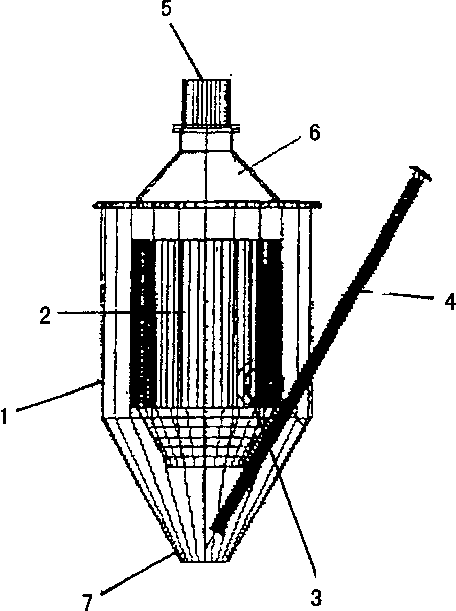
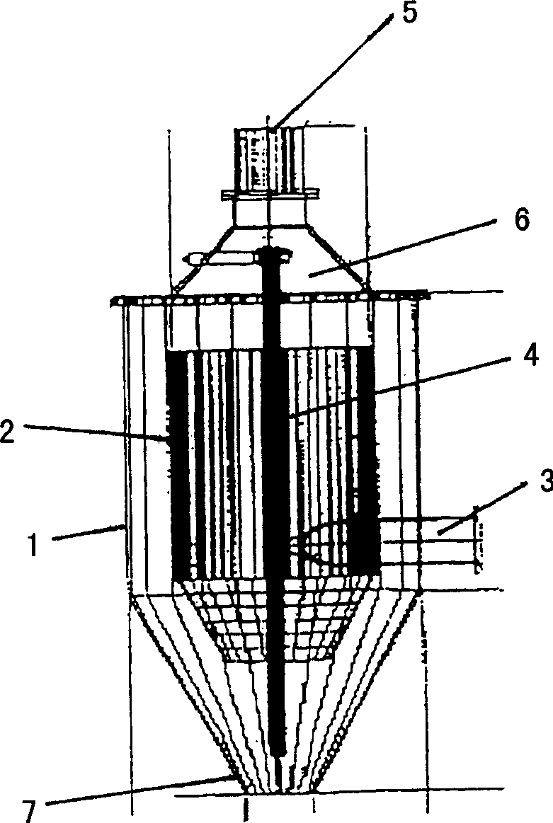
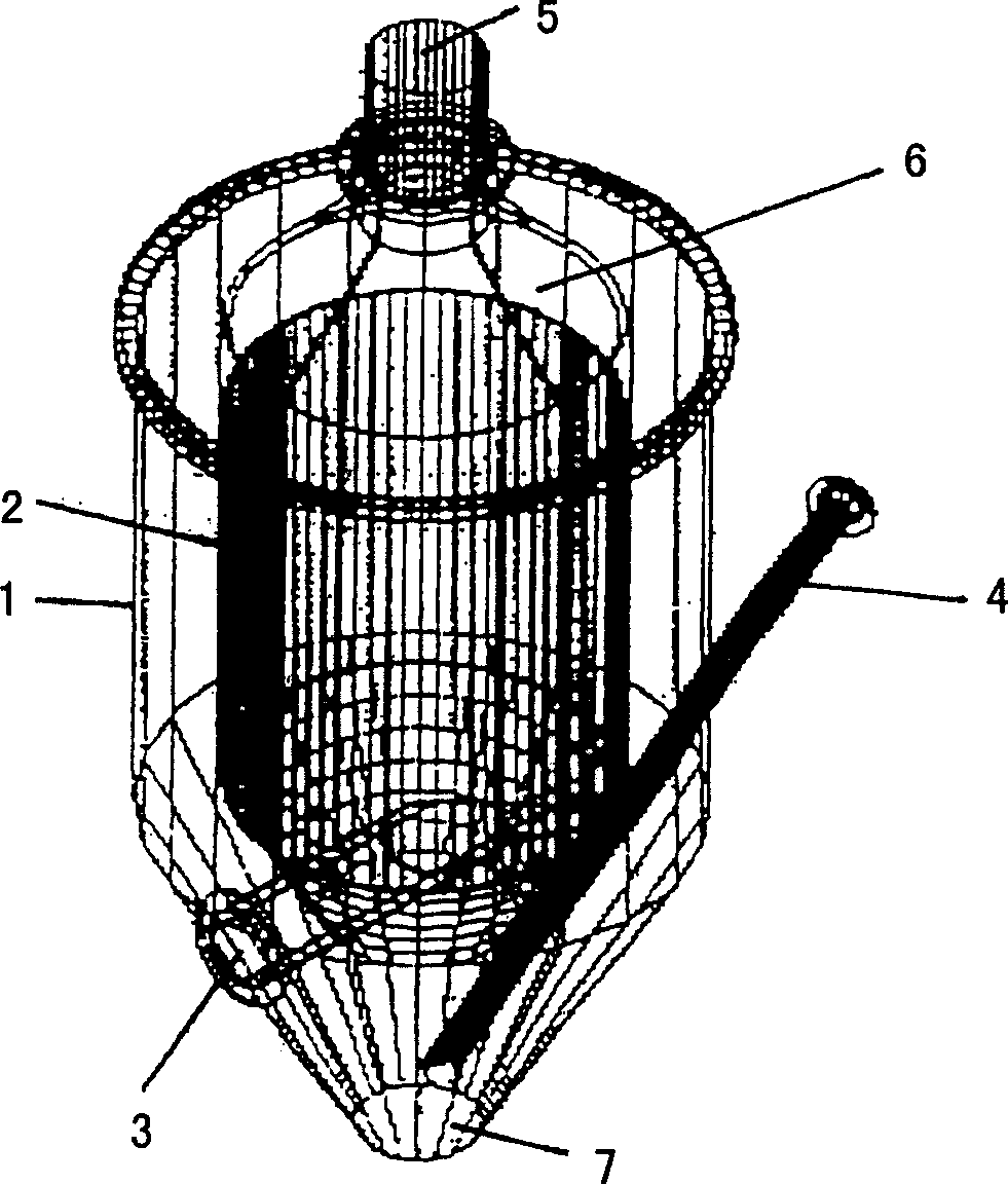
[0026] Each of these figures shows a different view of the same separation device. exist figure 1 In , the parts of the separation equipment are marked with reference numerals. The separating device has an outer base body 1 in which an inner body 2 is arranged. The base body 1 and the inner body 2 have an essentially cylindrical shape. The base body 1 is provided here with a conical bottom and a funnel tip 7 . The inner body 2 has a cone which is open downwards. Such as figure 2 As shown, the inlet 3 for the suspension is arranged eccentrically and constricts into a nozzle according to the permissible pressure loss. Discharge 5 for liquids containing hard-to-settle solids is arranged in the upper cover 6 . The cap 6 is conical and matches the diameter of the inner body 2 at the end. To optimize accessibility, the cover 6 is removable in one piece. In the conical bottom region of the base body 1 there is an outlet 4 for sludge containing easily settled solids.


PUM


Abstract

An assembly promotes the removal by sedimentation of solids arising from bioreactor fermentation. The separator has a cylindrical case (1) with a cylindrical insert (2) discharging to a conical base (7). The case has a side feed inlet (3) for incoming suspension. Substances that sediment poorly are drawn off through the conical cover outlet (5). Sedimented substances are drawn by tube (4) from the conical base. The inlet (3) is tangential to the cylindrical case and inclined downwards and terminates in a jet. The top outlet (5) is a trumpet-shaped removable cone (6) cover. The assembly re3ceives suspended solids from e.g. a refuse disposal system with fermenting bioreactor.

Description

technical field [0001] The invention relates to a separation device for suspensions. Background technique [0002] In the course of chemical engineering, the problem often arises that easily precipitable and difficult-to-precipitate solids must be separated from each other in a suspension. Especially during the operation of some bioreactors for the biological treatment of some suspensions such as sludge, manure, waste gas, etc., equipment technical problems often arise due to the deposition of sediment in the reactor. In order to save investment costs, for example, some digesters, fermentation reactors, etc. are often manufactured with flat or slightly conical bottoms. These bioreactors have some circulation systems in order to optimize the decomposition process and inhibit the deposition of precipitable substances. These circulatory systems can be constructed in various ways. As an example there may be mentioned the bioreactor described in WO 98 / 58070. In this reactor, ...

Claims


Application Information

Patent Timeline
Patent Type & Authority Applications(China)
IPC IPC(8): B03B5/38B01D21/26B03B5/34B04C5/103E03F5/14
CPCC02F1/38B03B5/34B01D21/267B01D21/02B01D21/2411B04C5/103B01D2221/06B01D21/26
Inventor 斯特芬·潘科夫
Owner LINDE KCA DRESDEN
Learn More